Technical Input Review
We review the model, drawing mark-ups, standards, templates, parts list and expected output. Missing tolerances, unclear notes and conflicting revisions are recorded before release work proceeds.
A model can describe shape, but manufacturing teams still need a controlled document that explains which features matter, how they are dimensioned and what approved requirements govern production and inspection. When tolerances, datums, finishes or material notes are incomplete, a visually polished drawing can create more uncertainty rather than less.
CAD Conversion Services India provides manufacturing drawing and GD&T services for manufacturers, mechanical engineering teams, equipment builders and product businesses. We prepare and update part, fabrication and assembly drawings in SolidWorks and AutoCAD using client-issued models, engineering requirements, templates and standards.
Our offshore team operates as a documentation resource. We can reproduce and organise approved dimensions, geometric controls, notes and specifications, but we do not independently select functional tolerances or certify whether a part can be manufactured or inspected. Those decisions remain with the client’s authorised engineers, quality personnel and production specialists.
Confirm these essentials before production begins.
Sketches, legacy drawings, samples, measurements and approved engineering instructions
Parts, assemblies, production drawings, BOMs and agreed exchange files
SolidWorks, AutoCAD and agreed mechanical CAD formats
Focused production support for Manufacturing Drawings and GD&T, with scope, source authority and review responsibility agreed before work begins.
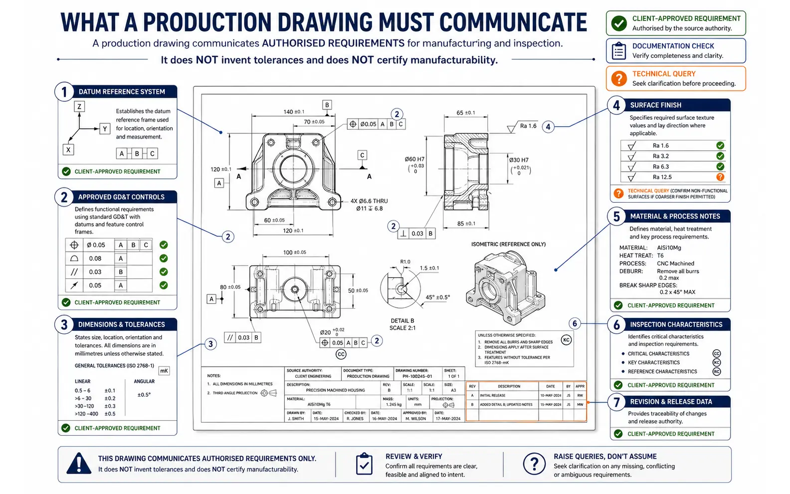
The content of a drawing depends on the component, manufacturing process and stage of release. A machined housing may require datums, sectional views and controlled hole relationships. A welded frame may need item references, weld information and interface dimensions. An inspection-focused sheet may present approved characteristics in a format suitable for quality planning.
Our capabilities can include:
The term “fabrication-ready” should be defined in the project brief. It may describe a completed drawing package containing all client-approved requirements, but it does not transfer engineering liability, manufacturing approval or process capability validation to the drafting team.
Good presentation helps a drawing communicate without duplication. We select and arrange orthographic views, sections, details, auxiliary views and isometric references according to the approved geometry and required information.
An expert drafter checks that dimensions attach to the intended features, that section and detail references are clear and that repeated values do not create contradictions. A professional reviewer compares the drawing against the supplied model, mark-up and technical instructions before submission.
We can follow client templates for sheet size, title blocks, projection method, units, scales, line conventions, drawing numbers and revision records. Any deviation required for a particular manufacturing or inspection workflow is documented during project setup.
For multi-sheet releases, an expert coordinator checks cross-references, part identifiers and revision alignment across the package. This professional coordination helps prevent administrative inconsistencies from reaching the client’s release review.
Dimensioned part drawings should present the approved definition clearly and at an appropriate level of detail. Baseline, ordinate, coordinate or conventional dimensioning can be followed according to client standards.
Surface finish annotations are entered from approved requirements and linked to the relevant features. General notes and feature-specific values are checked for consistency. Material, coating, heat-treatment and process instructions are reproduced only from authorised sources.
For fabricated items, drawings may include component references, cut information, assembly dimensions and client-issued weld and material specifications. The relevant symbol standard and shop conventions must be established before production.
Weld size, type, length, sequence and acceptance requirements involve engineering and manufacturing decisions. We document the approved information and flag gaps rather than choosing requirements that appear typical.
Inspection drawing preparation may involve identifying approved characteristics, organising balloon references and presenting information that supports a client’s first-article or quality-control process. The characteristic numbering method, inspection scope and required outputs are defined at setup.
We can help ensure that drawing identifiers, revision data and selected characteristics remain consistent with the released source. The client’s quality team remains responsible for inspection method, sampling, gauge capability, acceptance criteria and compliance with customer or regulatory requirements.
Tolerance stack documentation can also be prepared from client-supplied calculations, approved contributor dimensions and results. We do not infer stack relationships or calculate permitted limits without a separately agreed engineering brief.
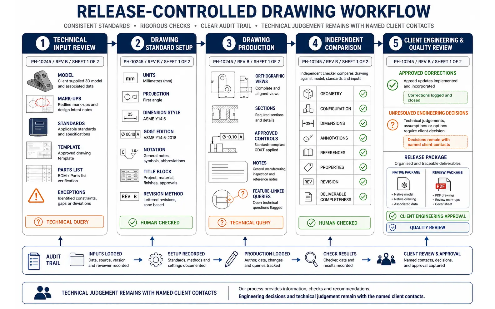
We review the model, drawing mark-ups, standards, templates, parts list and expected output. Missing tolerances, unclear notes and conflicting revisions are recorded before release work proceeds.
The team documents units, projection, dimension style, GD&T standard, notation rules, title-block fields, revision method and required native and review formats.
Views, dimensions, approved controls and notes are placed in the authorised drawing structure. Queries remain linked to the relevant sheet and feature.
Geometry, configuration, dimensions, annotations, references, properties and revision data are compared with the supplied sources. Deliverable completeness is checked separately.
Items requiring technical judgement are returned to the named client contacts. Approved corrections are incorporated before the final files are organised for release.
This process supports manufacturing drawing and GD&T outsourcing services while preserving the client’s established approval responsibilities.
AI-assisted tools may help extract title-block information, compare revision metadata, identify repeated notes and prepare lists of dimensions or annotations for validation. These capabilities can reduce repetitive setup on large drawing packages.
AI does not assign a tolerance, interpret an unclear datum, select a material or approve a drawing. A human drafter validates the content, and accountable reviewers compare the output with authorised instructions. This approach supports professional manufacturing drawing and GD&T services without making automation responsible for engineering decisions.
A fixed group of part, assembly or fabrication drawings can be scheduled around client review milestones and a known release date.
Companies can outsource manufacturing drawing and GD&T when design teams face a release backlog or need assistance converting approved models into controlled sheets.
Outsourced manufacturing drawing and GD&T support can manage continuing component releases, approved changes and drawing-standard updates. A current revision register helps prevent work against superseded inputs.
As an expert manufacturing drawing and GD&T service provider, we recommend starting with representative simple and complex drawings. This provides a realistic basis for confirming standards and review effort.
Manufacturing-drawing packages can be produced for international engineering and production teams, with units, drawing standards, approval gates and release dates defined for the destination facility. File transfer and review timing are agreed as part of the delivery plan.
Some organisations outsource a defined drawing package; others outsource selected documentation activities within an active engineering programme. Our team keeps open questions visible and separates production work from decisions that require engineering or quality authority.
The appropriate manufacturing drawing and GD&T solution depends on source maturity, part complexity, standards, inspection needs and review cycles. Businesses considering a manufacturing drawing and GD&T solutions company India can provide should assess technical-query handling and human checking as carefully as drawing throughput.
The team worked carefully from our approved mark-ups and did not attempt to reinterpret the datum structure. The updated drawings are much more consistent across the product range.
Jia Wei L., Manufacturing Engineering Manager, Singapore
Dense inspection drawings require patient comparison, and that is what we received. Questions were escalated to quality rather than being resolved through guesswork.
Nadine F., Supplier Quality Engineer, Switzerland
The weekly drawing queue has reduced pressure on our engineers. Sheets follow our release format, and open technical points remain clearly separated.
Ethan W., Mechanical Design Manager, Canada
Our standard scope is to document client-approved requirements. Datum selection, functional tolerance design and engineering analysis must be performed or approved by the client’s qualified engineer unless a separate engineering service is expressly agreed.
Yes. The applicable edition, client conventions, templates and approved interpretations should be provided before work begins.
Yes. We can create model-linked part and assembly drawings using approved models, configurations, properties and engineering instructions.
Yes. We can identify approved characteristics and prepare ballooned sheets and registers according to the client’s numbering method. Inspection strategy and acceptance criteria remain with the client’s quality team.
Share a representative model, drawing, engineering mark-up and applicable standard. We will review the information, identify missing instructions and define an appropriate drawing-production and checking workflow.
Request a Manufacturing Drawing Review