Source Reconciliation for Mechanical 3D Modeling Services
Drawing numbers, revisions, units and scales are checked. Conflicts between views or dimensions are listed for the client’s decision.
A three-dimensional model may be needed for design communication, assembly development, manufacturing documentation, retrofit planning or visual review. Those purposes are not interchangeable. A model created only to show external form may not contain the feature logic, internal detail or assembly relationships required for controlled engineering revisions.
CAD Conversion Services India provides mechanical 3D modeling services for manufacturers, product teams, engineering consultancies, equipment builders and fabrication businesses. Working mainly in SolidWorks, we create parts, assemblies and equipment models from approved drawings, sketches, mark-ups, measurements and other client-issued references.
Before production begins, we clarify what the model must support. The required geometry, feature structure, configurations, metadata, file relationships and drawing outputs are then documented. Our external-production role is to build the agreed CAD deliverable; engineering calculations, design validation, material selection and final approval remain with the client’s authorised professionals.
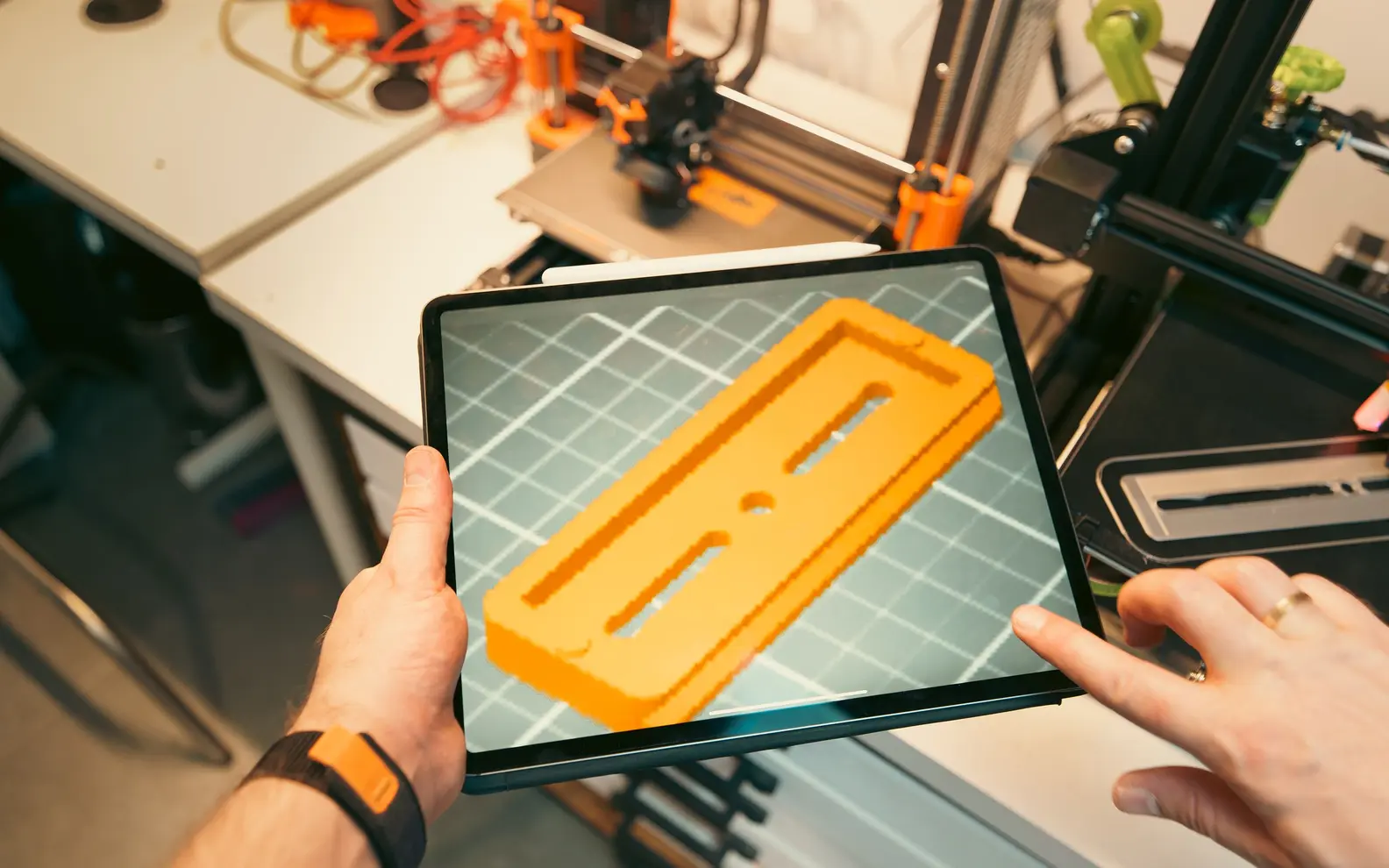
Confirm these essentials before production begins.
Sketches, legacy drawings, samples, measurements and approved engineering instructions
Parts, assemblies, production drawings, BOMs and agreed exchange files
SolidWorks, AutoCAD and agreed mechanical CAD formats
General mechanical 3D geometry and exchange outputs; use SolidWorks modeling when native parametric features are required.
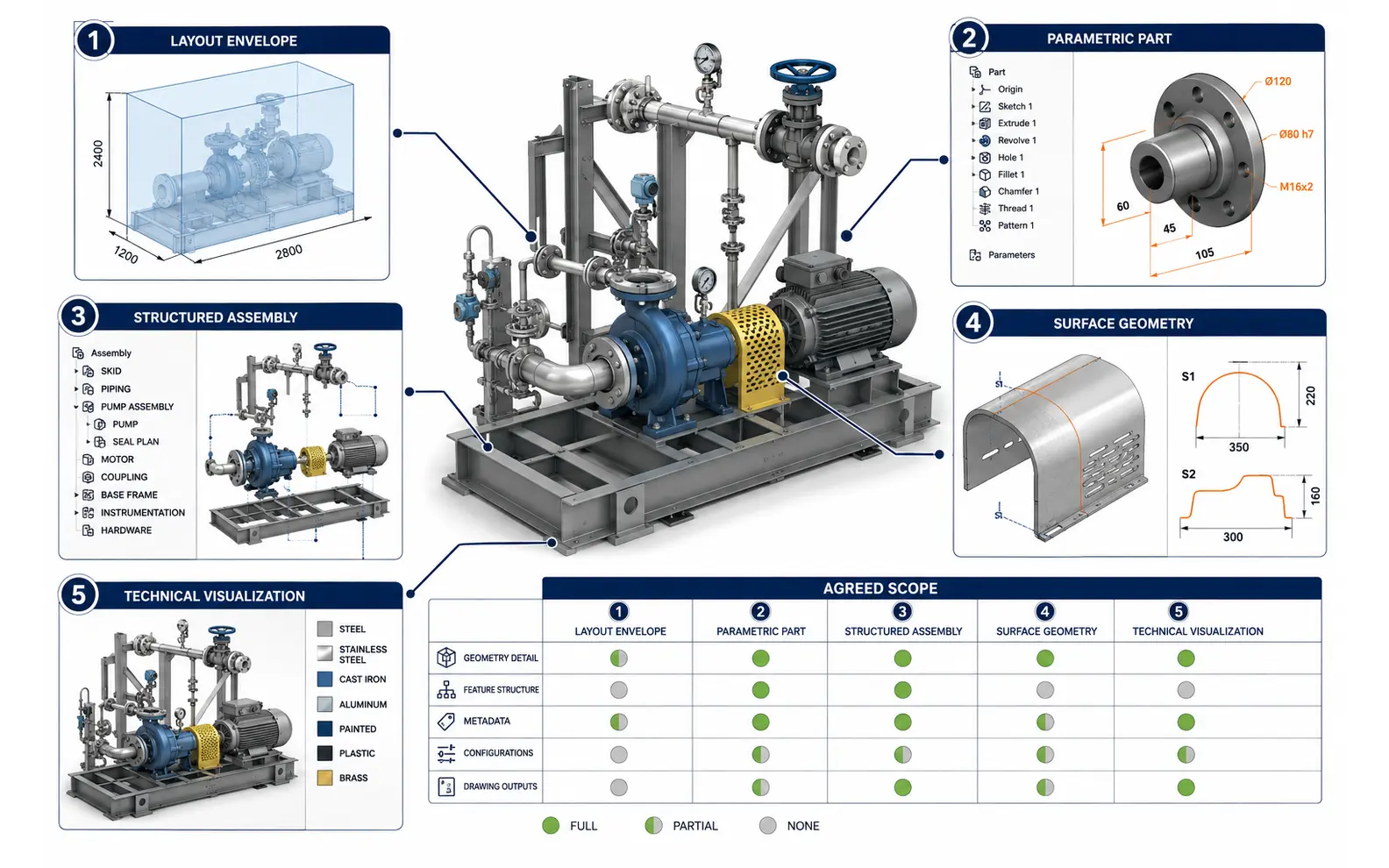
A useful scope starts with the question: what will happen after the model is delivered? An external envelope for equipment-layout coordination requires a different approach from a component that will undergo repeated dimensional changes. An assembly intended for an exploded view does not necessarily need the same information as one being reviewed for interfaces and maintenance access.
Our capabilities can include:
The phrase “manufacturing-ready” must be defined for each assignment. It may refer to complete solid geometry, model-linked drawings or approved fabrication information. It does not automatically mean that the part has been analysed, prototyped, tolerance-checked or certified for production.
For parts likely to change, feature strategy matters. A model can look correct on screen while remaining difficult to edit because references are unstable, features are poorly sequenced or design intent has not been documented.
Where the source information supports it, we create logical sketches, dimensions, reference geometry and features that reflect the agreed revision method. Names and custom properties can follow client conventions. An expert modeler also considers which dimensions are expected to change and which relationships must remain fixed, without independently deciding the engineering intent.
Mechanical assemblies can contain client-designed components, standard hardware, purchased items, weldments and supplier models. We organise those elements using the approved hierarchy and identifiers, create the required mates or positioning method and maintain references between files.
The scope may include subassemblies, configurations, simplified representations and exploded arrangements. Interference identification can be performed as a CAD check when requested, but any finding must be reviewed by the client. The absence of a detected interference is not a substitute for fit, tolerance-stack, motion, load or manufacturability validation.
Products with complex covers, housings, ducts or externally developed forms may require surface-based methods before a solid can be created. We can reconstruct approved geometry from suitable profiles, sections, measurements or scan-derived references.
Source quality is especially important for these assignments. Missing curvature definitions, incomplete transitions or distorted reference images are reported through queries. A professional model should reflect supplied information rather than disguise gaps with visually convenient assumptions.
For mixed part families, an expert coordinator also reviews whether naming, properties, reference geometry and assembly placement remain consistent across the package. This additional professional check is especially useful when several modelers contribute to one machine or product range.
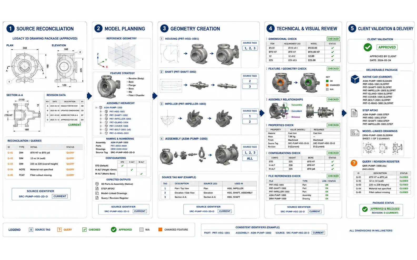
A legacy drawing can contain enough views to describe a component—or it may leave critical geometry open to interpretation. We review the available plans, elevations, sections, details and dimensions before committing to a 2D drawing to 3D mechanical model workflow.
The process normally includes:
Drawing numbers, revisions, units and scales are checked. Conflicts between views or dimensions are listed for the client’s decision.
The feature approach, assembly structure, file naming, configurations and expected deliverables are agreed. A representative model can be submitted first for a larger package.
Components are built from authorised information, and the model structure is kept consistent with the approved plan. Questions remain connected to the relevant feature or source drawing.
The completed geometry is compared with the source. Key dimensions, part relationships, feature states, properties, configurations and file references are reviewed within scope.
The client reviews design-dependent matters and provides correction instructions. Final native files and agreed exchange formats are then organised for delivery.
This sequence supports mechanical 3D modeling outsourcing services without allowing drafting assumptions to become undocumented design decisions.
AI-assisted tools may help classify source drawings, extract title-block information, compare revision lists, identify repeated components or prepare structured metadata for human validation. For a large component family, these capabilities can reduce administrative preparation and help expose inconsistencies earlier.
AI is not used to invent an internal feature, infer a critical dimension, choose a fit or approve a component. Geometry and extracted information remain subject to human review. Our professional mechanical 3D modeling services therefore combine selective automation with accountable CAD production and client-controlled engineering judgement.
A fixed assignment may cover one product, a machine station, a component family or a known assembly. Scope can be divided into review milestones so the hierarchy and model detail are confirmed before the complete package is built.
Companies can outsource mechanical 3D modeling when their engineers are occupied with design decisions, testing, customer changes or commissioning. Clearly separated work packages allow the external team to focus on approved production tasks.
Outsourced mechanical 3D modeling support can handle recurring component additions, drawing-to-model conversions and approved revisions. A current instruction set and controlled intake register help maintain consistency between batches.
As an expert mechanical 3D modeling service provider, we recommend testing standards with a representative part or subassembly when the source condition, product family or feature expectations are unfamiliar.
We provide external-production mechanical 3D modeling services from India to clients in the United States, Canada, European nations, the United Arab Emirates, Australia, South Africa, Singapore, Japan, Taiwan and India. Delivery arrangements can reflect the client’s time zone, software version, file-transfer procedure and review schedule.
Some organisations outsource a one-time conversion package; others delegate selected model-production activities within an active engineering programme. Our team separates CAD execution from matters requiring design authority and keeps technical queries visible throughout the assignment.
The appropriate mechanical 3D modeling solution depends on model purpose, source completeness, component volume, assembly complexity and expected revision behaviour. Organisations evaluating a mechanical 3D modeling solutions company India can provide should also assess checking methods, file organisation and the ability to follow existing CAD standards—not price alone.
The staged assembly reviews were valuable because our installed machine did not always match the archive. The team kept confirmed geometry and open questions clearly separated.
Luca B., Retrofit Engineering Manager, Italy
We now have a configuration structure our engineers can understand and maintain. The modeling team followed the rules we approved instead of trying to redesign the product family.
Thabo M., Product Engineering Supervisor, South Africa
The weekly batches have reduced interruptions for our design group. Model properties and file names are consistent, and questions arrive with enough detail for a quick decision.
Rebecca T., Mechanical Engineering Lead, United States
We can assess 2D CAD drawings, PDFs, scans, sketches, redlines, existing 3D files, photographs and measurement or scan-derived information. Suitability depends on whether the sources define the geometry needed for the intended model.
Yes, when the drawings contain adequate dimensions and views. Feature strategy and expected revision behaviour should be discussed before production, especially for configurable parts or component families.
Not automatically. Manufacturability depends on approved materials, tolerances, processes, calculations, testing and supplier capability. Our core scope is model and documentation production under client-issued engineering requirements.
Yes. The required software release, templates, file names, properties, feature conventions, part numbers and exchange formats should be included in the project instructions.
Send a representative drawing, sketch, assembly or existing model and explain how the completed files will be used. We will review the available information, identify open questions and recommend a suitable production workflow.
Request a Mechanical 3D Modeling Review