Structural 3D Modeling Services for Clearer Geometry and Coordination
Two-dimensional drawings can describe a structure accurately, yet complex offsets, intersections and level changes may remain difficult to understand until the project is viewed spatially. Our structural 3D modeling services convert approved structural information into organised models for coordination, visualization and drawing production.
Projects may begin with CAD plans, PDFs, sketches, survey data, point-cloud references or existing discipline models. CAD Conversion Services India defines the model purpose before building geometry so the result supports an actual project task rather than becoming a decorative representation.
AutoCAD and Revit provide the core environment for building projects, while SolidWorks can support suitable fabricated components. AI-assisted comparison may help identify discrepancies, but an experienced modeler checks every issued result.
✓ AI Powered✓ Free Pilot Batch✓ NDA Protected✓ 99.5% Quality
1500+Completed Projects
82%Returning Clients
10+Years Experience
45+Countries Served
35+Professionals Team
Project Fit at a Glance
Confirm these essentials before production begins.
Inputs
Engineer-issued design information, calculations, mark-ups and project standards
Outputs & deliverables
Structural models, drawings, schedules and material-specific detailing
Software
AutoCAD, Revit and agreed structural-production tools
Service intent
Focused production support for Structural 3D Modeling Services, with scope, source authority and review responsibility agreed before work begins.
IndustriesArchitectureConstructionManufacturingEngineeringReal EstateCountries ServedUSACanadaUKAustraliaUAEEuropean Nations45+ Countries
IndustriesArchitectureConstructionManufacturingEngineeringReal EstateCountries ServedUSACanadaUKAustraliaUAEEuropean Nations45+ Countries
Three-Dimensional Geometry with a Stated Use
A coordination model, presentation model and fabrication-ready structural model do not contain the same information. The scope should identify who will use the file, what decisions it supports and which elements are reliable at the current issue.
We establish:
Source drawings and their revision hierarchy
Intended model use and project phase
Structural elements to include or exclude
Required geometric accuracy and tolerances
Coordinates, grids and level references
Naming, classification and parameter needs
Interfaces with architecture, MEP or equipment
Required views, drawings and exchange formats
Review ownership and approval status
This foundation ties the structural model to defined deliverables, avoiding the impression that every visible component has automatically been designed or approved.
Steel and Concrete Model Development
3D Structural Steel Model
A 3D structural steel model may include columns, beams, bracing, trusses, secondary steel, stairs and approved connection geometry. Member sizes, orientations, offsets and relationships are checked against the latest structural information.
The model can be used for visual review, space coordination, drawing views and agreed fabrication support. Connections or member changes that require engineering judgement remain subject to approved calculations and the responsible engineer.
Concrete Structure 3D Model
A concrete structure 3D model can represent foundations, walls, columns, beams, slabs, cores, ramps and major openings. Geometry is organised around project grids and levels so sections and coordination views remain consistent.
Reinforcement, construction joints, embeds and pour-specific information are included only when the source information and scope support them. Accurate concrete geometry does not establish reinforcement adequacy or construction sequence by itself.
Structural Frame Modeling for Complex Arrangements
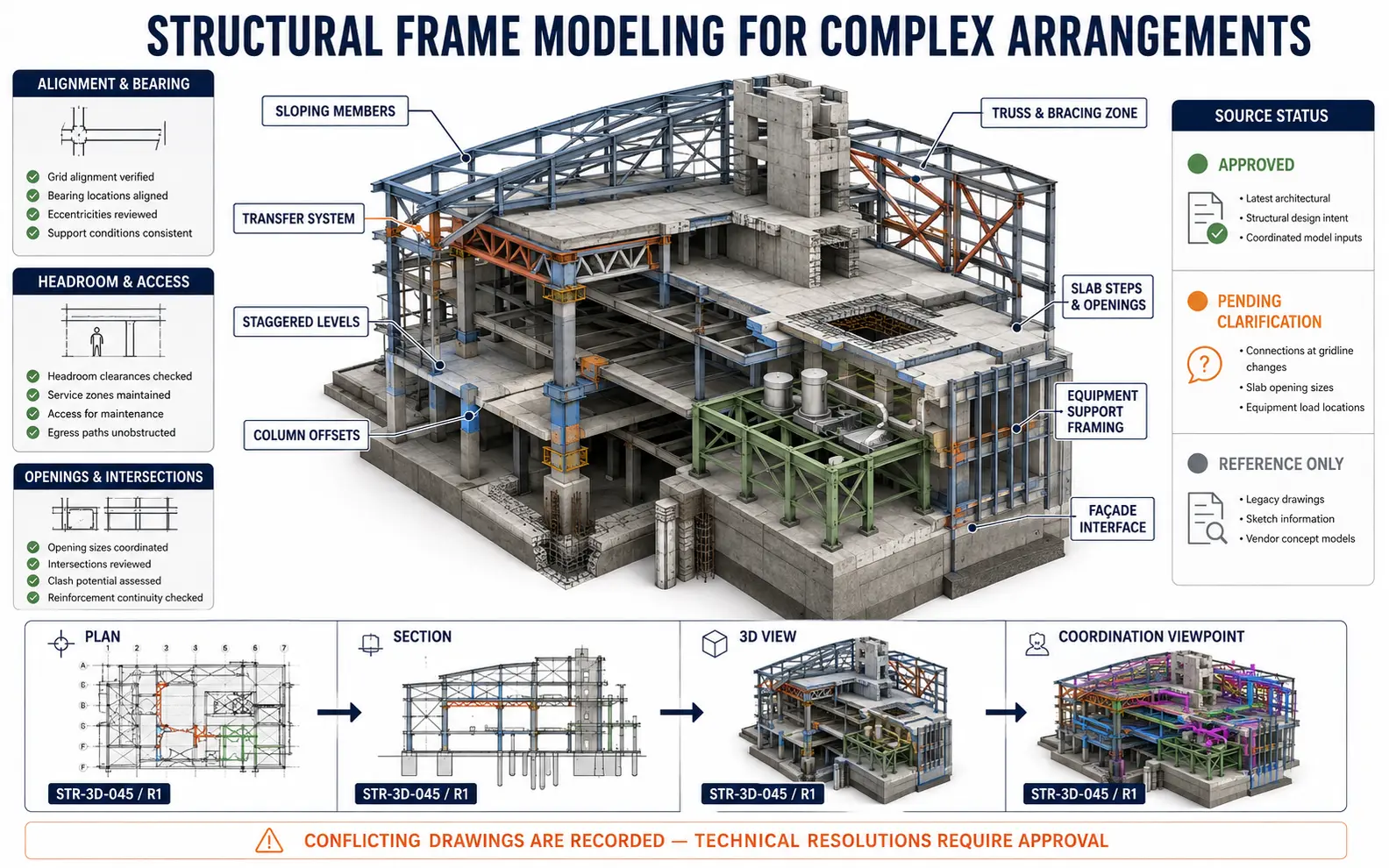
Structural frame modeling is valuable where the building contains sloping members, transfer systems, trusses, staggered levels or dense interfaces. A spatial model can reveal relationships that are difficult to follow across separate plans and sections.
Beam column slab modeling can help teams review:
Member alignment and bearing relationships
Slab edges, steps and openings
Beam depth and headroom conditions
Column offsets between floors
Bracing zones and façade interfaces
Transfer members and discontinuities
Equipment loads and support framing
Roof geometry and drainage falls
The modeler records inconsistencies instead of choosing which conflicting drawing should control. Technical resolutions are incorporated only after approval by the nominated client contact or engineer.
Revit Structural 3D Models and Information Control
A Revit structural 3D model can combine geometry with categories, types, parameters, views and schedules. The amount of information is set by the model’s intended use rather than by filling every available field.
Our team can establish grids, levels, worksets, linked files, browser organisation and model naming according to client standards. Required elements may be separated by zone, building, material or issue status when this improves coordination and file management.
A coordinated structural model can then support plans, elevations, sections, schedules and exchange files. An experienced reviewer checks that the 2D outputs accurately represent the issued model state and that hidden or linked information has not been omitted unintentionally.
Converting 2D Drawings into Structural 3D
The process of converting 2D drawings to structural 3D involves more than tracing plan lines and assigning heights. Plans, sections, details and schedules must be reconciled to understand the intended geometry.
Typical input challenges include:
Different levels shown across drawing issues
Missing sections through complex areas
Legacy member names that do not match schedules
Unclear offsets or beam orientation
Scanned information with limited dimensional reliability
Uncoordinated architectural and structural openings
Later redlines not reflected in the base files
We register these conditions in a query log. A representative zone can be modeled first, allowing the client to confirm interpretation, presentation and level of detail before the remaining structure is developed.
Visualization That Supports Technical Discussion
Structural visualization can make geometry easier to explain to project managers, fabricators, contractors and non-modeling stakeholders. Isolated views, colour-coded zones, cutaways and sequencing snapshots can clarify how members relate to one another.
Visuals may support:
Design and constructability workshops
Coordination meetings
Fabrication or erection planning
Existing-condition reviews
Option comparisons using approved alternatives
Client presentations and technical reports
Visualization is a communication aid, not an engineering certificate. A convincing perspective can still contain incorrect assumptions, so every view remains tied to the model’s stated status and source information.
Constructability and Fabrication-Oriented Models
A constructability model can help identify access restrictions, geometric congestion and interfaces that may affect assembly or installation. The review can examine how approved members, plates, openings and adjacent systems occupy the same space.
When the assignment requires a fabrication-ready structural model, the scope defines connection status, component detail, tolerances, member marking and required production data. Fabrication use is not inferred merely because the model contains small components.
The qualified production team can prepare drawing views, component references and exchange files based on approved design information. Fabrication methods, erection sequencing, temporary stability and site safety remain with the authorised contractor and engineers unless separately included.
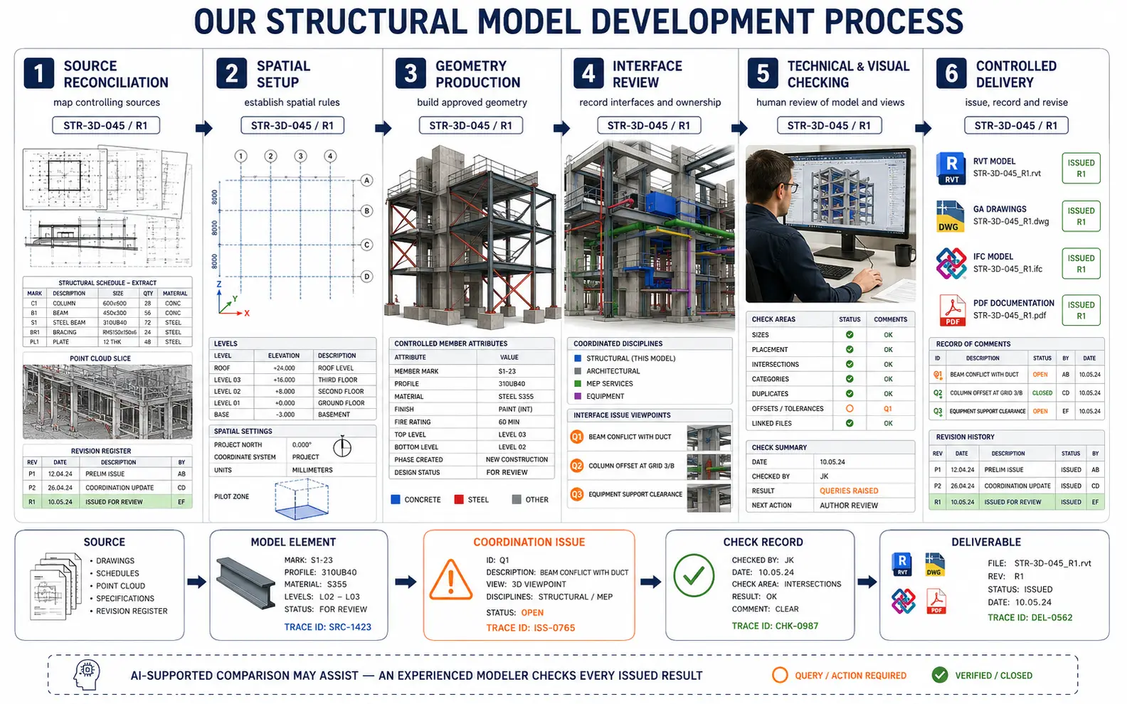
Our Structural Model Development Process
Source Reconciliation
Plans, sections, schedules, models and revisions are mapped so the team knows which information controls each area.
Spatial Setup
Coordinates, grids, levels, units, model divisions and naming conventions are established. A pilot zone can be used to confirm interpretation.
Geometry Production
Modelers create the agreed structural elements and attributes. Approved source references remain traceable during development.
Interface Review
Relevant architectural, services, equipment or fabrication information is compared with the structure. Issues are recorded with viewpoints and ownership.
Technical and Visual Checking
An experienced checker reviews member sizes, placement, intersections, categories, duplicates, offsets, linked files and deliverable completeness. AI-supported comparisons may assist with large revisions.
Controlled Delivery
Models, drawings and views are issued in the agreed formats and status. Approved comments are incorporated through recorded revision cycles.
Model Checks Before Issue
Depending on scope, review may cover:
Units, coordinates, grids and levels
Member sizes, materials and orientation
Slab, wall and foundation geometry
Joins, intersections and duplicated elements
Openings, embeds and approved penetrations
Categories, types and naming consistency
Required parameters and schedule population
Linked-model position and visibility
Model warnings and unresolved queries
Drawing-view and model agreement
File names, revisions and issue status
The checking process verifies representation against approved information. Structural analysis, member adequacy and local compliance remain separate engineering responsibilities.
Additional Capacity for Modeling-Intensive Projects
Our modeling team can assist with one-time conversions, coordination backlogs or continuing model updates. Work packages are organised by building zone, material, model milestone or client priority.
External model production can provide temporary or recurring capacity without diverting senior internal staff to repetitive geometry work. The client retains technical control, source authority and approval responsibility.
We keep questions and model limitations visible and deliver controlled files rather than relying on undocumented assumptions.
The delivery arrangement can follow the client’s communication, security and common-data-environment requirements across international time zones.
Structural 3D Modeling Services Project Case Studies
Project 1: Steel Model for a Semiconductor Utility Building
Volume
1,460 structural members across five equipment zones
Problem
A Taiwanese project team had separate steel plans, equipment layouts and service-routing models for a utility building. Dense overhead systems made it difficult to evaluate bracing, access platforms and major pipe routes through 2D overlays.
Solution
We created a zoned steel model from the approved member schedules, then linked equipment and service references using the project coordinates. Rather than reporting every intersection, the team grouped issues by access, structure, piping and incomplete design information. Approved changes were incorporated through controlled model releases.
Outcome
Coordination meetings could focus on meaningful interfaces instead of interpreting multiple overlays. The project team received spatial views for congested zones while structural decisions remained with its appointed engineers.
Title
BIM Coordination Manager
Industry
Semiconductor Facilities
Country
Taiwan
Project 2: Existing Concrete Model for a Hotel Renovation
A South African renovation consultant inherited incomplete archive drawings and a point-cloud survey showing that several columns, slab edges and stair openings differed from the original plans. The design team needed a usable existing-condition reference without disguising uncertain areas as surveyed facts.
Solution
We separated verified geometry, drawing-derived geometry and unresolved locations through parameters and view filters. Modelers built the concrete frame floor by floor, using survey slices where available and the archive set elsewhere. A confidence register directed the consultant to areas requiring further site measurement.
Outcome
The consultant obtained a practical renovation model with visible information reliability. New-design coordination could begin in confirmed areas while survey gaps remained easy to identify and manage.
Title
Renovation Project Architect
Industry
Hospitality and Real Estate
Country
South Africa
Project 3: Recurring Structural Model Updates for Modular Buildings
Volume
8–12 module configurations per month
Problem
A United States modular-building manufacturer continually adapted standard frames for different openings, equipment loads and transport constraints. Internal engineers approved the changes, but repetitive model and drawing updates were delaying production releases.
Solution
We established controlled base models and a change-request sheet for each configuration. Modelers applied engineer-approved frame changes, regenerated affected views and checked member references against the production register. Deviations without approval were isolated instead of being merged into the standard library.
Outcome
The manufacturer shortened routine update cycles while protecting its approved base configurations. Engineers reviewed defined deviations, and production teams received model and drawing releases with clear configuration identifiers.
Title
Product Engineering Manager
Industry
Modular Construction Manufacturing
Country
United States
Structural 3D Modeling Services Client Feedback
“
The zoned views changed how we ran coordination meetings. We could discuss the difficult interfaces immediately instead of searching through separate plans.
Yu-Ting C., BIM Coordination Manager, Taiwan
“
The confidence register was especially valuable. It showed our team where the model came from survey evidence and where further verification was still needed.
Naledi P., Renovation Project Architect, South Africa
“
Recurring updates now reach production with the correct configuration reference. Our engineers can concentrate on the deviations that actually require approval.
Jason K., Product Engineering Manager, United States
Questions About Structural 3D Modeling Services
Can you create a structural model from scanned drawings?+
Yes, if the drawings are sufficiently legible and contain usable dimensions or scale references. Unclear or contradictory geometry is recorded for clarification. Scanned sources are not treated as verified site conditions unless the client confirms them.
Is a 3D model the same as a BIM model?+
Not necessarily. A 3D model may primarily communicate geometry, while a BIM model usually includes structured information, classifications, relationships and defined project uses. We agree the required content before production.
Can your model be used directly for fabrication?+
Only when fabrication use is expressly included and the required engineering, connection, component and tolerance information has been approved. Otherwise, the file remains a coordination or documentation model.
Which model formats can you deliver?+
Depending on the workflow, outputs may include RVT, DWG, IFC, PDF and agreed neutral exchange formats. Native versions, coordinates, file divisions and required supporting drawings are confirmed during scoping.
Show Us the Geometry That Is Difficult to Coordinate
Send representative plans, sections, models, survey references, required outputs and the intended use. We will assess the inputs, identify uncertainties and recommend a suitable qualified modeling approach.
Whether you want to assign externally a fixed conversion package or add continuing offshore capacity, the model should remain connected to approved information and a defined review process.