Mechanical and SolidWorks Services / Technical Production

Weldment and Fabrication Drawing Services for Controlled Production

A welded frame may look straightforward on a general arrangement, yet the fabrication package behind it has to communicate far more than its overall size. Profiles, member lengths, mitres, plate positions, hole patterns, weld references and assembly relationships must all agree. When those details are scattered across sketches, legacy drawings and marked-up files, shop teams lose time resolving questions that should have been settled before release.

CAD Conversion Services India provides weldment and fabrication drawing services for manufacturers, fabricators, equipment builders and engineering teams. Using SolidWorks and AutoCAD, we turn client-approved design information into organised 3D weldment models, cut lists, welded assembly drawings and fabrication-ready CAD drawings. Our offshore team works within the supplied engineering rules; it does not select structural members, calculate weld capacity or approve the finished design.

Companies can assign externally weldment and fabrication drawing work when internal designers need reliable production capacity without handing over engineering authority. We establish the required templates, profile libraries, drawing conventions and review points before volume work begins. Each package is checked by an experienced team member, and artificial intelligence may assist with file classification, metadata extraction or revision comparison where appropriate.

The result is a practical weldment and fabrication drawing solution built around traceable source information and human technical control.
✓ AI Powered✓ Free Pilot Batch✓ NDA Protected✓ 99.5% Quality
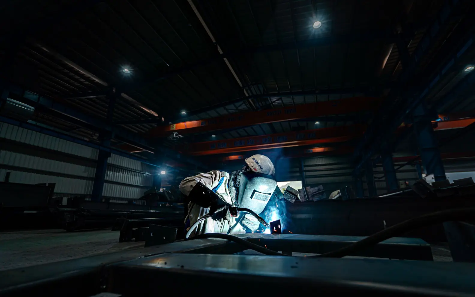
Welder joining a large steel structure inside an industrial fabrication workshop
Industrial steel fabrication
1500+Completed Projects
82%Returning Clients
10+Years Experience
45+Countries Served
35+Professionals Team

Project Fit at a Glance

Confirm these essentials before production begins.

Inputs

Sketches, legacy drawings, samples, measurements and approved engineering instructions

Outputs & deliverables

Parts, assemblies, production drawings, BOMs and agreed exchange files

Software

SolidWorks, AutoCAD and agreed mechanical CAD formats

Service intent

Focused production support for Weldment and Fabrication Drawings, with scope, source authority and review responsibility agreed before work begins.

IndustriesArchitectureConstructionManufacturingEngineeringReal EstateCountries ServedUSACanadaUKAustraliaUAEEuropean Nations45+ Countries

From Approved Geometry to Shop-Usable Information

Our work can begin with native SolidWorks files, 2D CAD drawings, PDFs, redline mark-ups, hand sketches, point measurements or a mixture of references. Before modeling starts, we identify which source is authoritative and which details require clarification. That distinction matters when an older drawing conflicts with a newer bill of materials or when a sketch shows geometry without a confirmed profile.

The production scope can include:

  • SolidWorks weldment modeling for frames, skids, guards, platforms and equipment supports
  • Structural frame weldments built with approved profile libraries
  • Tube and pipe frame modeling from client-issued dimensions
  • Welded assembly drawings with orthographic and detail views
  • Fabrication shop drawings for individual members, plates and subassemblies
  • Cut list preparation with item marks, quantities and approved descriptions
  • Weld symbol drawings based on client-provided welding requirements
  • Steel frame fabrication drawings with sections and connection details
  • Production weld drawings for workshop review
  • Material and profile schedules derived from the approved model
  • DXF or DWG outputs where flat or 2D production data is required

This is a documentation service, not a substitute for engineering design. Section sizes, grades, connection design, welding procedures, tolerances, coatings, load criteria and compliance requirements remain subject to approval by the client’s engineer, fabricator or other authorised qualified.

What a Coordinated Weldment Package Can Contain

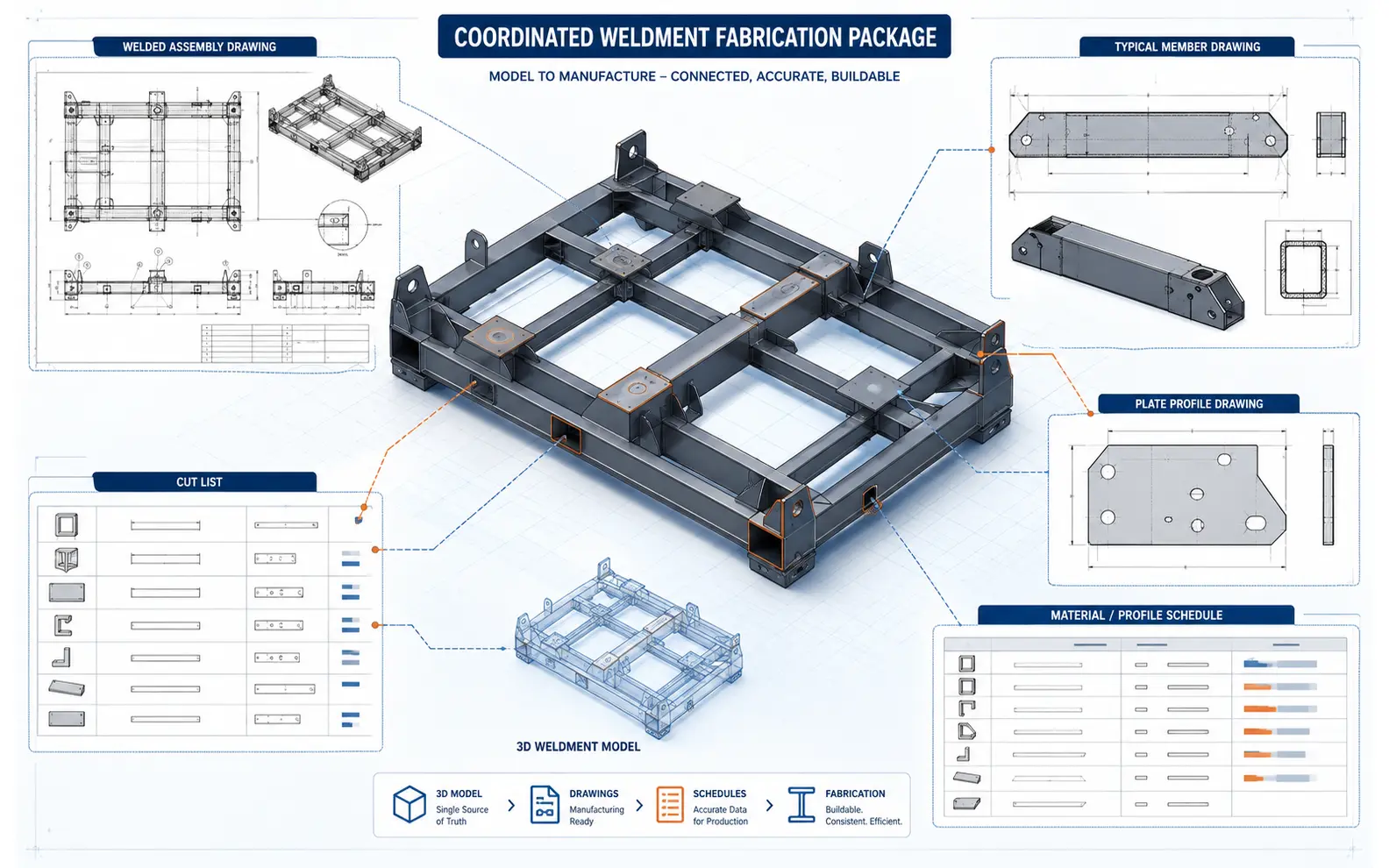
Coordinated weldment package connecting a steel equipment skid model with assembly drawings, member details, plate profiles, cut lists and material schedules
A controlled weldment model keeps member details, assembly sheets, plate profiles, cut lists and material schedules connected to the same approved geometry.

The 3D Weldment Model

The model establishes the geometric relationship between structural members, plates and purchased components. We can create multibody weldment parts, trim or extend members, manage corner treatments and organise bodies into a cut list. For larger equipment, logical subassemblies can make review and downstream documentation easier.

Model construction follows the intended use. A frame required only for drawing production may need a different level of detail from one used for interference checking, mass review or downstream manufacturing data. We agree that purpose first so unnecessary features are not added and required information is not omitted.

Individual and Assembly Drawings

Individual drawings can show member lengths, end conditions, hole locations, plate geometry and formed features. Welded assembly drawings communicate how those items relate, using dimensions, sections, detail views and approved weld references. Where the fabricator uses a defined sheet sequence or numbering system, we apply it consistently.

Ballooning and item identification are coordinated with the bill of materials or cut list. A drawing should not call an item one name while the schedule uses another. Our check therefore covers cross-references as well as graphic presentation.

Cut Lists and Schedules

SolidWorks cut lists can capture profile descriptions, quantities, finished lengths, angles, material references and item numbers. Fields are mapped to the client’s approved properties rather than populated through assumptions. We can also prepare material and profile schedules in the required drawing or spreadsheet format.

Automated properties save time only when the underlying model and templates are controlled. We verify that identical bodies are grouped correctly, descriptions are readable and the schedule agrees with the views. Final purchasing quantities, stock allowances and nesting decisions remain with the client or fabricator.

A Production Workflow Built Around Fabrication Questions

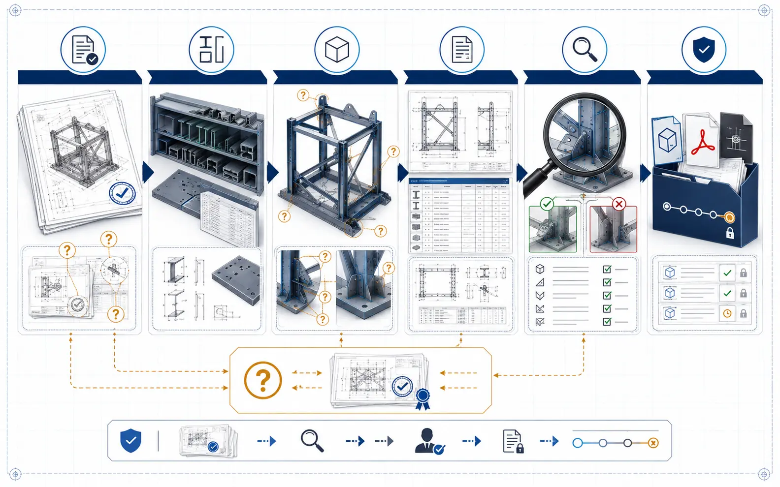
Six-stage weldment documentation workflow covering source review, profile setup, modeling, drawing production, human checking and revision-controlled delivery
Undefined fabrication details become traceable queries while approved inputs move through profile setup, modeling, drawing production, independent checking and controlled delivery.

1. Source and Standards Review

We examine the design files, mark-ups, typical details, title blocks and release requirements. Units, model origin, profile naming, drawing scale, decimal precision, weld notation standard and deliverable formats are recorded. Conflicts are listed for the authorised contact instead of being silently resolved.

2. Profile and Template Setup

Approved profiles are matched to the relevant SolidWorks weldment library or created as controlled project profiles. Custom properties, cut-list fields, sheet formats and drawing notes are tested on a small sample. This setup is especially important for recurring production, because one inconsistent property can propagate across many drawings.

3. Model Construction

Members and plates are modeled from the accepted geometry. Trim conditions, gaps, offsets and body grouping are applied according to the project instructions. Purchased components may be inserted at the agreed level of simplification. Anything affecting function or manufacturability that is not defined is raised as a query.

4. Drawing and Schedule Development

Views are selected to explain the work without crowding the sheet. Dimensions, item marks, section indicators, approved notes and weld callouts are added. Cut lists and bills of materials are then generated from controlled model properties and formatted to the client’s standard.

5. Human-Reviewed Checking

Our qualified checking process compares the drawing package with the accepted sources and the model. Review points may include overall dimensions, member lengths, part quantities, hole positions, item references, model-to-drawing consistency, schedule population and sheet completeness. AI-assisted comparisons may help locate changes between revisions, but a person assesses the result.

6. Submission and Revision Control

Files are issued in the agreed native and exchange formats. Client comments are logged against the relevant drawing or model revision. When an instruction changes the design basis, we wait for authorised direction before updating connected deliverables.

Checks That Reduce Workshop Ambiguity

Our technical review is designed to find documentation errors and unclear information before delivery. Depending on scope, it may verify:

  • Model and drawing units
  • Consistency between overall, subassembly and member dimensions
  • Cut-list item marks and quantities
  • Correct use of approved profile descriptions
  • Hole, slot and plate-feature locations against the source
  • Visibility of sections, details and hidden features
  • Agreement between balloons, views and schedules
  • Required sheet names, drawing numbers and revision fields
  • Referenced files and drawing dependencies
  • Completeness of native, PDF, DWG or DXF deliverables

The review does not certify structural adequacy, welding procedure suitability, fatigue life, regulatory compliance or site fit. Those decisions belong to the client’s appointed technical authorities. This boundary keeps our role clear while allowing our team to operate as a dependable experienced weldment and fabrication drawing service provider.

Flexible Support for Different Fabrication Workloads

Fixed Drawing Packages for Weldment and Fabrication Drawings

A defined package suits a machine frame, access platform, equipment skid or known group of welded assemblies. After a sample and query review, the production plan can be set around a specific model and drawing list.

Archive Conversion and Standardisation

Older workshop drawings may need to be rebuilt in SolidWorks, reorganised into a new template or converted into a consistent model-and-drawing structure. We preserve approved design intent while documenting information that cannot be confirmed from the source.

Recurring Drawing Capacity

For manufacturers with frequent variants, our offshore weldment and fabrication drawing services can be arranged as scheduled work packages. A shared instruction register, controlled templates and agreed query process help maintain consistency as jobs change. This ongoing arrangement is useful when internal engineering staff want to concentrate on design, calculations and approval.

Why Outsource This Work to CCSI?

The value is not simply lower drafting effort. A structured external workflow can help a business separate design decisions from document production, clear a drawing backlog and create repeatable outputs from inconsistent source files.

Clients choose our weldment and fabrication drawing outsourcing services to gain scalable support, software-appropriate allocation and documented clarification. We can align with established drawing practices without claiming authority we have not been given. The engagement may cover a single frame or outsourced weldment and fabrication drawing support for an ongoing product line.

Before production, we agree who answers design queries, who approves the sample and what constitutes final acceptance. qualified weldment and fabrication drawing services may cover one frame or an ongoing product line while release responsibility remains with the client.

Weldment and Fabrication Drawings Project Case Studies

Modular Process-Skid Frame Documentation

Project Name
Modular Process-Skid Frame Documentation
Volume
14 skid frames, 186 fabricated items and 62 drawing sheets
Problem
A US equipment integrator had approved layout models but its frame documentation mixed generic profile names, disconnected plate drawings and manually maintained cut lists. Workshop questions were delaying release.
Solution
Our offshore production team rebuilt the frames as controlled SolidWorks weldments, mapped approved custom properties, developed member and assembly sheets and generated coordinated cut lists. Conflicting connection dimensions were logged for the client engineer.
Outcome
The client received a consistent release package with traceable item marks and fewer schedule-to-drawing mismatches. The engineering team retained approval of profiles, welds and load requirements.
Title
Mechanical Engineering Manager
Industry
Process Equipment
Country
United States

Stainless-Steel Guarding Drawing Recovery

Project Name
Stainless-Steel Guarding Drawing Recovery
Volume
37 guard assemblies and 112 legacy PDFs
Problem
An Australian automation builder needed editable documentation for safety guards that had evolved through workshop mark-ups. Several PDFs lacked native models, and repeated frames used inconsistent part identifiers.
Solution
The client chose to outsource the reconstruction package. We modeled the approved tube geometry, separated repeatable panels, prepared fabrication drawings and flagged missing latch and clearance details. A professional sample review established the drawing style before the remaining guards were processed.
Outcome
The recovered models and drawings created a maintainable baseline for future client-approved revisions without implying validation of guarding compliance.
Title
Production Engineering Lead
Industry
Factory Automation
Country
Australia

Recurring Agricultural-Frame Drawing Support

Project Name
Recurring Agricultural-Frame Drawing Support
Volume
8–15 frame variants per month
Problem
A Canadian machinery company regularly released product variants, but its internal detailers could not keep pace with drawing updates and cut-list checks during seasonal peaks.
Solution
We established a controlled queue using the company’s SolidWorks templates, profile library and revision rules. An expert checker compared each variant with the approved engineering mark-up, while unresolved functional changes were returned to the client.
Outcome
Monthly releases became more predictable, and the internal team kept responsibility for design decisions, prototype evaluation and manufacturing release.
Title
Senior Product Designer
Industry
Agricultural Machinery
Country
Canada

Weldment and Fabrication Drawings Client Feedback

Questions About Weldment and Fabrication Drawings

Can you create drawings from PDFs or marked-up sketches?

Yes. We can review PDFs, scans, sketches and redlines alongside available CAD data. Suitability depends on legibility and completeness. Undefined dimensions, profiles, joints or weld requirements are submitted for clarification rather than inferred.

Do you specify weld sizes, materials or structural members?

No. We document approved requirements supplied by the client. Selection and validation of materials, sections, welds, connections, tolerances and compliance criteria remain with the authorised engineer or fabricator.

Can you follow our SolidWorks profiles and drawing templates?

Yes. Client libraries, custom properties, sheet formats, cut-list rules and numbering conventions can be incorporated. We normally test them on a limited package before broader production.

Can we outsource recurring frame variants as well as one-time projects?

Yes. Both engagement types are available. For repeat work, we recommend controlled templates, an instruction register, a defined approver and a clear method for identifying changes. The appropriate approach depends on volume, complexity and release frequency.

Prepare the Next Fabrication Package with Clearer Control

Whether you need steel frame fabrication drawings for one equipment package or continuing capacity for production weld drawings, begin with a representative model, drawing or mark-up. Tell us the required SolidWorks version, output formats, applicable standards and approval contact. We will review the inputs, identify gaps and propose a qualified production path suited to your fabrication workflow.

Request a Weldment Drawing Review
QuickQuote