Mechanical and SolidWorks Services / Technical Production
Exploded View and Assembly Drawing Services for Clear Product Communication
An assembly model explains where components exist; it does not automatically explain how people should identify, install, remove or replace them. A useful exploded view must separate parts clearly, preserve their relationship and support the task. Too little separation creates clutter; too much can obscure the sequence.
CAD Conversion Services India provides exploded view and assembly drawing services for manufacturers, product developers, maintenance teams and technical publishers. We create SolidWorks exploded views, ballooned assembly drawings, assembly sequence documentation and parts identification drawings from client-approved product data. Our external-production specialists can support documentation teams without taking responsibility for product design, installation safety or release approval.
Clients may outsource exploded view and assembly drawing work when engineering models are available but internal resources are focused on development or production. We organise the source assemblies, confirm the intended audience and establish the illustration standard before scaling the work. Every deliverable receives human review, with AI-assisted comparison or file classification used only where it adds controlled efficiency.
The service provides a practical exploded view and assembly drawing solution for turning complex product structures into purposeful visual information.
✓ AI Powered✓ Free Pilot Batch✓ NDA Protected✓ 99.5% Quality
1500+Completed Projects
82%Returning Clients
10+Years Experience
45+Countries Served
35+Professionals Team
Project Fit at a Glance
Confirm these essentials before production begins.
Inputs
Sketches, legacy drawings, samples, measurements and approved engineering instructions
Outputs & deliverables
Parts, assemblies, production drawings, BOMs and agreed exchange files
Software
SolidWorks, AutoCAD and agreed mechanical CAD formats
Service intent
Focused production support for Exploded Views and Assembly Drawings, with scope, source authority and review responsibility agreed before work begins.
IndustriesArchitectureConstructionManufacturingEngineeringReal EstateCountries ServedUSACanadaUKAustraliaUAEEuropean Nations45+ Countries
IndustriesArchitectureConstructionManufacturingEngineeringReal EstateCountries ServedUSACanadaUKAustraliaUAEEuropean Nations45+ Countries
One Assembly Can Require Several Different Explanations
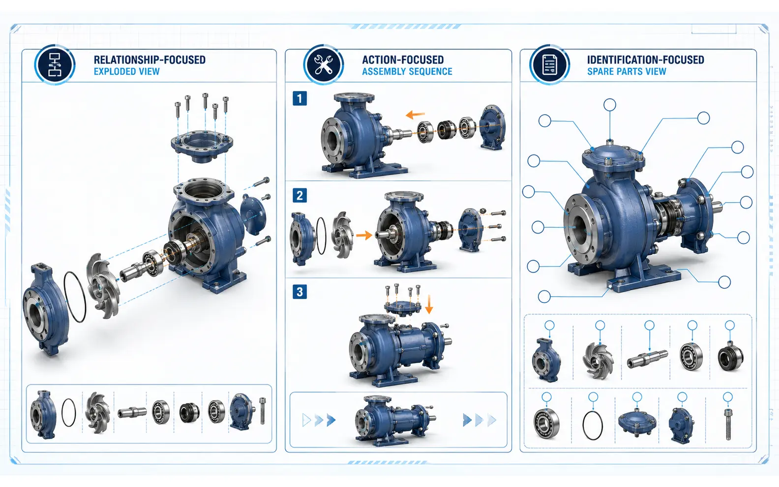
The same product may need one drawing for workshop assembly, another for installation and a third for spare-parts identification. One image rarely serves all three well. We first identify the user and required action.
Our scope can include:
Exploded assembly drawings for products, machinery and equipment
Assembly instruction drawings with ordered steps
Ballooned assembly drawings linked to an approved bill of materials
Product installation drawings based on client-defined procedures
Parts identification drawings for service teams and distributors
Technical illustration services for manuals and digital content
Assembly sequence documentation for controlled build stages
Maintenance manual drawings showing approved access or replacement steps
SolidWorks exploded views with explode lines and saved configurations
Disassembly diagrams for authorised service procedures
Spare parts catalog drawings with item references
Simplified 2D outputs in PDF, DWG, DXF or image formats
Our role is documentation production. The client remains responsible for confirming assembly order, torque values, tools, fasteners, adhesives, clearances, hazards, lifting methods, service isolation, regulatory statements and any other instruction affecting safety or performance.
Choosing the Right Visual Structure
Exploded Views for Product Relationships
An exploded view separates components while preserving a recognisable relationship to the assembled product. We can build linear, radial or staged explode steps, depending on geometry and the approved communication goal. Explode lines may be added where movement would otherwise be ambiguous.
Large assemblies often become clearer when divided into logical subassemblies. A single view containing hundreds of balloons is rarely useful. We can prepare overview, subassembly and detail illustrations that follow the approved product hierarchy and keep item identification readable.
Assembly Instructions for Action
Assembly instruction drawings need more than separated parts. They may require a sequence, orientation cues, fastener references, enlarged details and short approved notes. We arrange views so the progression is easy to follow, while the client defines the technically correct order and procedure.
Where steps repeat, we can establish reusable layouts and illustration conventions. Hands, tools, arrows or caution markers require approved guidance. We do not invent an installation method from geometry alone.
Catalog Illustrations for Identification
Spare parts catalog drawings help users match visible components to item numbers and approved descriptions. Unnecessary internal detail can be suppressed so the relevant parts remain legible. Balloons, leader lines and tables are coordinated to avoid crossings and duplicate references.
The source bill of materials is treated as controlled information. If model names, part numbers and the approved list disagree, we report the conflict. We do not decide which component should be stocked, substituted or sold.
Inputs We Can Work With
Native SolidWorks assemblies usually provide the richest starting point, including hierarchy, configurations and metadata. We can also review STEP, Parasolid and other neutral 3D files, existing 2D drawings, PDFs, photographs, redlines and approved parts lists. Each format carries different limitations.
A neutral model may lose mates, configurations or properties. A PDF may show a parts list without the full assembly relationship. Photographs clarify appearance but are not dimensional authority unless supported by measured references. Our expert review identifies these limitations during scoping.
Before production, we typically confirm:
Intended audience and document purpose
Authoritative assembly revision and configuration
Approved bill of materials or parts list
Required assembly or disassembly sequence
Items to show, hide, simplify or group
Balloon, item-number and leader conventions
Required page size, view style and image resolution
Language, terminology and approved notes
Native and published deliverable formats
Person responsible for technical clarification and release
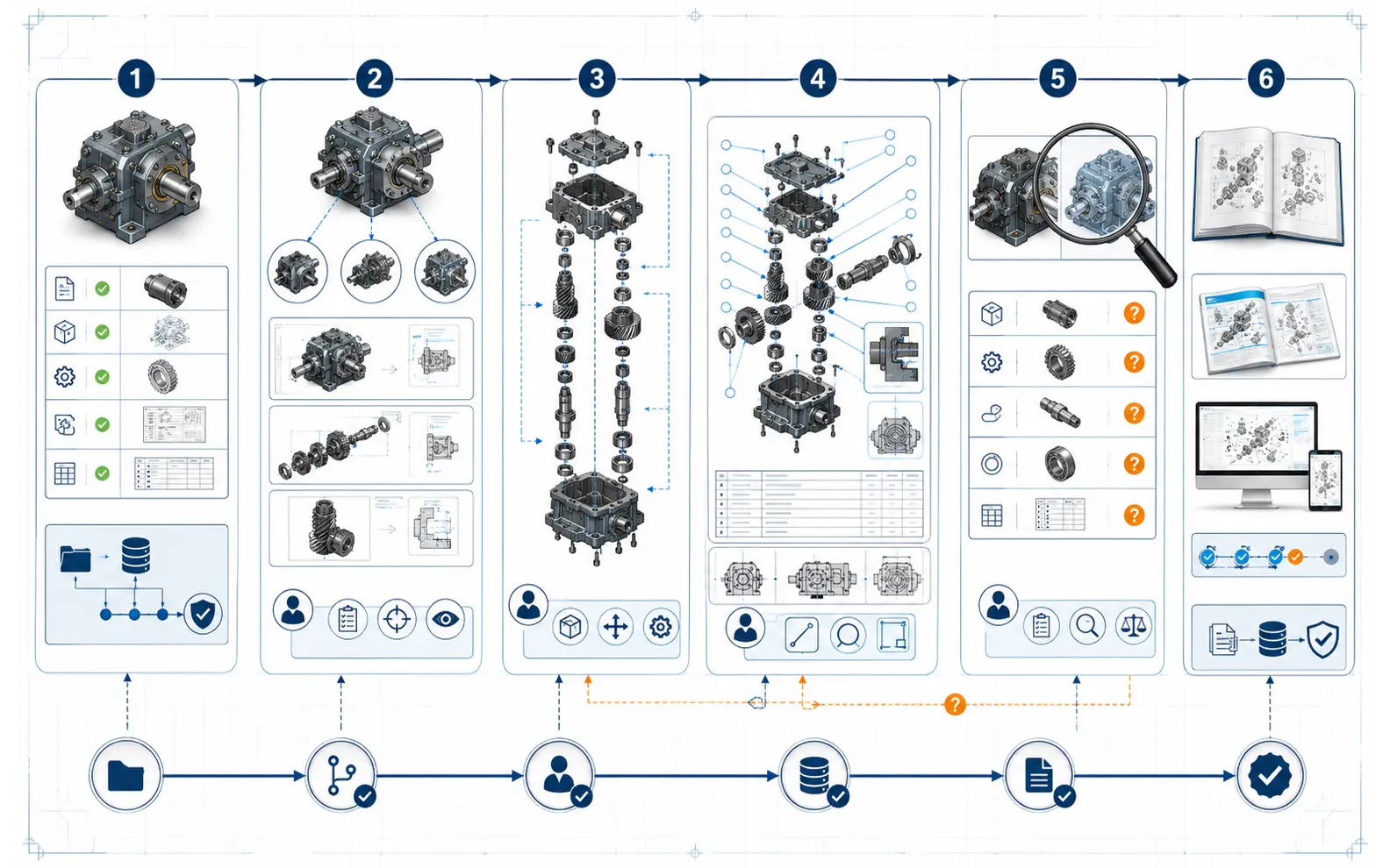
A Human-Controlled Illustration Workflow
1. Assembly Health and Source Review
We check that supplied files open with the expected references and configurations. Missing components, suppressed items, unresolved links and duplicate part identifiers are recorded. For large datasets, AI may help classify files or compare lists, but a team member validates what enters production.
2. Communication Plan
The drawing list is organised around the user task. We decide with the client whether the package needs an overview, staged sequences, subassembly sheets, catalog plates or a combination. A representative sample confirms the visual language before full development.
3. View and Configuration Development
Approved models are simplified at the agreed level. Explode steps are created, components are spaced, orientations are selected and explode lines are added where necessary. Saved configurations help separate documentation states from the design assembly.
4. Annotation and Page Composition
Item balloons, arrows, step numbers, callouts and approved notes are arranged for clarity. Tables are populated from the controlled parts information. Technical illustration services can also provide clean raster or vector-style outputs for publication, depending on the source and requested format.
5. Professional Quality Review
The review checks component visibility, item-number consistency, leader placement, orientation, sequence continuity, page references, image clarity and output completeness. It also compares the illustration with the approved assembly configuration. Questions about function or procedure return to the client’s authorised expert.
6. Publication and Revision
Native files and final outputs are delivered in the agreed structure. Revisions are applied against a recorded source version so a changed model is not confused with a layout adjustment. Release for manufacturing, installation or public use remains with the client.
Details That Make Assembly Drawings Easier to Use
Clear composition is partly about what is left out. Cosmetic hardware, repeated fasteners or background components may be simplified when the approved purpose allows it. Conversely, a small washer or orientation feature may need an enlarged view because it affects identification.
Our checking can cover:
Completeness of visible components against the selected configuration
Agreement between balloons and the approved parts list
Duplicate or missing item references
Readability of leader routes and explode lines
Consistent perspective and orientation across steps
Logical division of large assemblies into subassemblies
Cross-references between overview, step and detail pages
Image resolution, line quality and page fit
File names, revision identifiers and publication structure
These checks improve documentation quality but do not validate whether the assembly procedure is safe, efficient or technically correct. The client’s engineering and product teams approve those matters.
Support Models for Product Documentation Teams
A Defined Manual or Catalog Package
A fixed scope works well for a new product launch, maintenance manual, installation guide or parts catalog. The source configuration, illustration list and submission format are defined before production, with an early sample for approval.
Documentation Recovery
Legacy products may have usable CAD assemblies but outdated illustrations, or manuals may contain images that no longer match current part numbers. We can reconstruct the publication set around approved revision data and record discrepancies that need client resolution.
Recurring Product Updates
An external-production exploded view and assembly drawing services workflow can support companies that release variants, engineering changes or new service kits throughout the year. Controlled styles, view conventions and change logs make each new package easier to integrate. This ongoing solution provides production continuity while the internal team controls engineering and publication approval.
When Outsourcing Adds Practical Capacity
Exploded view and assembly drawing outsourcing services are useful when the documentation backlog is larger than the available illustration team, or when engineers are spending too much time composing publication graphics. External production can also standardise outputs created at different times by different authors.
CCSI can act as an expert exploded view and assembly drawing service provider within the client’s established process. The team can follow approved templates, item rules and terminology for a one-time assignment or provide outsourced exploded view and assembly drawing support across recurring releases.
The decision to outsource should include clear ownership. We agree the source revision, reviewer, query channel and acceptance point at the beginning. That allows a professional exploded view and assembly drawing services engagement to add capacity without blurring responsibility for product instructions.
Exploded Views and Assembly Drawings Project Case Studies
Packaging-Machine Assembly Manual Illustrations
Project Name
Packaging-Machine Assembly Manual Illustrations
Volume
1 master machine, 28 subassemblies and 74 instruction figures
Problem
A German equipment manufacturer had a complete SolidWorks assembly, but its manual relied on workshop screenshots with inconsistent orientations and no controlled link to the bill of materials.
Solution
Our offshore team created saved explode configurations, divided the machine into logical build stages and prepared assembly instruction drawings with approved item references. Procedure notes and torque requirements were supplied and approved by the client.
Outcome
The publication team received a coherent illustration set that was easier to place in the manual and update after approved model revisions.
Title
Technical Documentation Manager
Industry
Packaging Machinery
Country
Germany
Consumer-Product Spare Parts Catalog
Project Name
Consumer-Product Spare Parts Catalog
Volume
42 product variants and 318 catalog illustrations
Problem
A Singapore distributor needed clear spare parts catalog drawings for a family of appliances, but variant assemblies contained reused components, inconsistent descriptions and internal geometry irrelevant to customers.
Solution
The company chose to outsource exploded view and assembly drawing production. We applied the approved product hierarchy, simplified non-serviceable detail, laid out readable balloons and reconciled item references against the client-issued catalog list. Conflicts were returned for product-team decisions.
Outcome
The final catalog plates presented a consistent identification system across all variants while preserving the client’s control over part availability and substitution.
Title
Regional After-Sales Manager
Industry
Consumer Appliances
Country
Singapore
Monthly Service-Kit Illustration Updates
Project Name
Monthly Service-Kit Illustration Updates
Volume
10–18 changed kits per month
Problem
A UK industrial pump company issued frequent service-kit revisions, and its in-house technical authors were struggling to update disassembly diagrams alongside manual text and release records.
Solution
We created a recurring queue using approved SolidWorks configurations, catalog styles and change notices. An expert reviewer checked balloons, component visibility and page references, while the client’s service engineers approved removal sequences and safety notes.
Outcome
Illustration updates became a predictable part of the monthly publication cycle, and outdated kit images were identified before manual release.
Title
Service Documentation Lead
Industry
Industrial Pumps
Country
United Kingdom
Exploded Views and Assembly Drawings Client Feedback
“
The illustrations now use the same orientation and item logic throughout the manual. Their questions also helped us catch two places where our procedure notes did not match the latest assembly.
Lukas H., Documentation Engineering Lead, Germany
“
CCSI handled the repetitive illustration work carefully and did not hide conflicts in the product data. Our team could approve the catalog knowing which references had been checked.
Mei Lin T., Product Support Manager, Singapore
“
The monthly queue fits our change process well. We still control every service instruction, while the drawing team keeps the graphics and references organised.
Oliver P., Technical Publications Manager, United Kingdom
Questions About Exploded Views and Assembly Drawings
Can you create exploded drawings from STEP files?+
Yes, provided the file contains sufficient assembly structure or the client can identify the required component relationships. Neutral files may not retain mates, configurations or custom properties, so we assess their limitations before confirming scope.
Do you develop the assembly or disassembly procedure?+
No. We visually document a sequence approved by the client. Engineering teams must confirm order, tools, torque, safety precautions, access requirements and all instructions affecting product performance or user safety.
Can the drawings be used in manuals and spare-parts catalogs?+
Yes. We can prepare product installation drawings, maintenance manual drawings, parts identification drawings and publication-ready images. Page dimensions, resolution, language and output format should be agreed before production.
Can you maintain drawings when products change regularly?+
Yes. Recurring support can be based on approved engineering changes, source revisions and a controlled publication schedule. The best workflow includes a named approver and a clear rule for replacing obsolete configurations.
Turn Approved Assemblies into Usable Visual Instructions
Send us a representative SolidWorks assembly, parts list and example of the intended publication style. Explain whether the audience is a workshop, installer, service technician or customer. We will review the model structure, identify missing information and propose a professional workflow for clear assembly and product documentation.