Mechanical and SolidWorks Services / Technical Production
Mechanical 2D Drafting Services for Clear, Controlled Production Drawings
A mechanical drawing has to communicate more than the outline of a component. It must present the correct views, dimensions, notes, references and revision status in a format that engineers, machinists, fabricators and inspectors can interpret consistently. When source information is fragmented or the drawing queue grows faster than internal capacity, disciplined drafting support can keep documentation moving without shifting design authority.
CAD Conversion Services India provides mechanical 2D drafting services for manufacturers, equipment builders, engineering firms and product teams. We prepare and update mechanical engineering drawings in AutoCAD from approved sketches, models, PDFs, scans, redlines and legacy files.
Our offshore team works to client-issued standards and reports unclear information for resolution. We do not infer missing tolerances, approve materials or certify whether a component is fit for manufacture. Those responsibilities remain with the authorised engineers and production specialists who control the design.
✓ AI Powered✓ Free Pilot Batch✓ NDA Protected✓ 99.5% Quality
1500+Completed Projects
82%Returning Clients
10+Years Experience
45+Countries Served
35+Professionals Team
Project Fit at a Glance
Confirm these essentials before production begins.
Inputs
Sketches, legacy drawings, samples, measurements and approved engineering instructions
Outputs & deliverables
Parts, assemblies, production drawings, BOMs and agreed exchange files
Software
SolidWorks, AutoCAD and agreed mechanical CAD formats
Service intent
Controlled 2D mechanical drawings; use 3D or SolidWorks modeling when a reusable parametric model is required.
IndustriesArchitectureConstructionManufacturingEngineeringReal EstateCountries ServedUSACanadaUKAustraliaUAEEuropean Nations45+ Countries
IndustriesArchitectureConstructionManufacturingEngineeringReal EstateCountries ServedUSACanadaUKAustraliaUAEEuropean Nations45+ Countries
2D Drawings for Parts, Assemblies and Fabricated Equipment
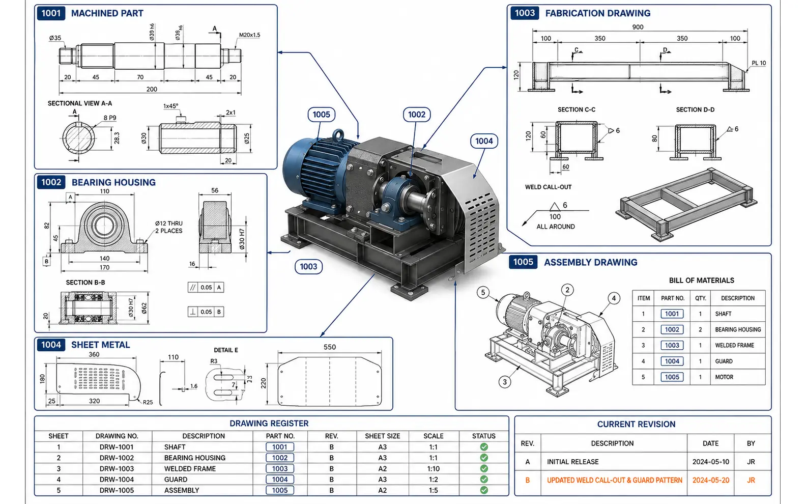
The content of a drawing should match its intended use. A machinist may need unambiguous dimensions, datums and finish requirements. A fabricator may need material references, weld information and interface details. An assembly technician may need item identification, sectional views and a relationship to the bill of materials.
Our scope can include:
Machine part drawings for turned, milled and manufactured components
Assembly drawings showing item relationships and client-supplied identifiers
Fabrication drawings for frames, brackets, guards and fabricated equipment
Machining drawings prepared from approved geometry and engineering notes
AutoCAD mechanical drafting using client templates, layers and dimension styles
Dimensioned technical drawings with orthographic, detail and auxiliary views
Orthographic projection drawings for components and equipment
Sectional mechanical drawings that clarify hidden or internal features
Production drawing services for controlled manufacturing-document packages
Legacy mechanical drawing updates and file standardisation
Drawing recreation from legible paper, scan, image or PDF sources
We can deliver native DWG files and agreed exchange or review formats. Sheet size, units, projection method, revision convention, drawing numbering and software version are defined before production begins.
From Source Geometry to an Usable Drawing Set
Creating Drawings from Approved 3D Models
Client-issued 3D models can provide the geometry for 2D views, but they do not automatically supply every manufacturing requirement. We generate the required view arrangement and incorporate approved dimensions, notes, tolerances and identifiers from the engineering brief. Where the model and written instruction conflict, the discrepancy is raised rather than resolved by assumption.
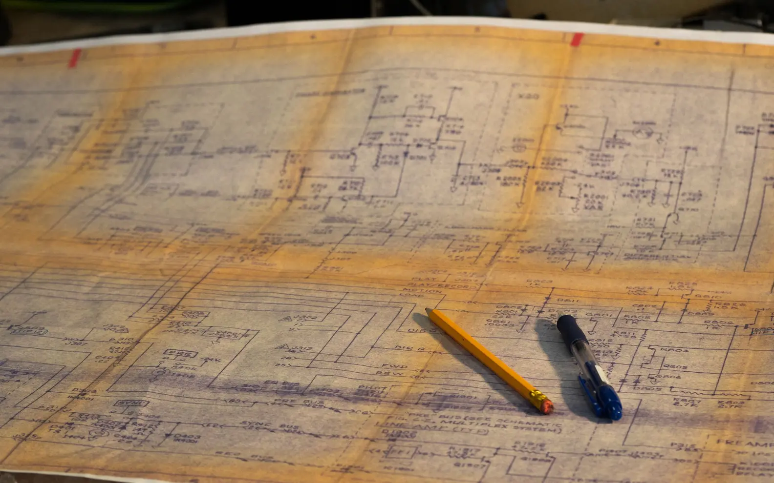
Redrawing Legacy Paper, Scan and PDF Records
Older mechanical records may contain skewed scans, faded dimensions, manual revisions or inconsistent drawing conventions. We recreate legible geometry in AutoCAD and rebuild the sheet using the approved template. Ambiguous characters, missing dimensions and contradictory notes are captured in a query log.
Updating Existing CAD Drawings
For revision work, we first confirm the current base file and applicable mark-up. Changes are incorporated with the client’s revision method, while unaffected information is preserved. This is especially important when several redline sets exist or a drawing has been modified by different teams over time.
Standardising Mixed Drawing Archives
Files from acquired products, suppliers or older departments can be organised around a common structure. Titles, layers, text, dimension styles and identifiers may be standardised within scope, but technical content remains tied to the approved source.
View Selection and Drawing Presentation
A clear drawing uses enough information to define the approved component without crowding the sheet. Depending on the geometry, we can prepare front, top and side views, sections, details, auxiliary views and isometric references. View scale, hidden-line treatment and annotation placement are coordinated for readability.
An experienced drafter checks that dimensions are attached to the intended features and that repeated information does not create avoidable contradictions. A qualified reviewer then compares the completed sheet with the source package and confirms drawing number, revision, units, title-block data and deliverable completeness.
For multi-sheet packages, an experienced coordinator also checks whether part numbers, view references and assembly identifiers remain consistent from one document to the next. This qualified review helps prevent administrative mismatches from entering the client’s release process.
We reproduce client-issued GD&T symbols, tolerances, finishes, weld symbols and material specifications when they are supplied and approved. Our drafting role does not extend to selecting those requirements or validating the underlying engineering calculation.
Our Mechanical 2D Drawing Workflow
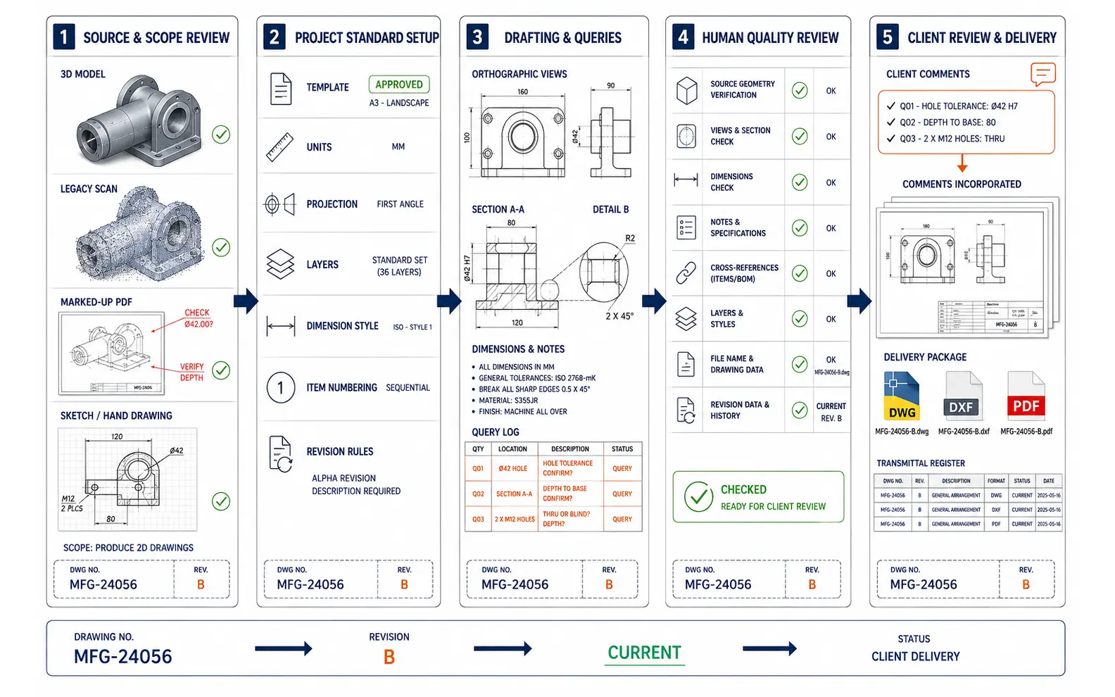
1. Source and Scope Review
We examine representative files, expected sheets, output formats and intended use. Unreadable or conflicting information is identified before the drawing queue is committed.
2. Project Standard Setup
The team records units, projection method, templates, layers, text and dimension styles, numbering, revision rules and delivery structure. A sample sheet can be prepared for approval when appropriate.
3. Drafting and Query Management
Drawings are produced from the authorised references. Questions are logged with enough context for the client’s engineer to answer without searching through the entire package.
4. Human Quality Review
The output is compared against source geometry and instructions. Checks can cover views, dimensions, notes, cross-references, layer use, sheet presentation, file naming and revision data.
5. Client Review and Delivery
Client comments are incorporated according to the agreed review cycle. Final native and review files are organised using the approved transmittal structure.
This controlled sequence makes our mechanical 2D drafting outsourcing services suitable for both one-time drawing packages and recurring production queues.
AI Assistance without Uncontrolled Assumptions
For large drawing sets, AI-assisted tools may help read title blocks through OCR, classify file types, compare revision metadata, find repeated notes and flag inconsistencies in file names. These tasks can reduce preparation time, particularly when an archive contains hundreds of records.
AI does not decide whether a blurred dimension is 6 or 8, create a missing tolerance or determine which conflicting revision is technically correct. A human drafter validates extracted information, and an accountable checker reviews the output. That combination supports qualified mechanical 2D drafting services without transferring engineering judgement to automation.
Flexible Capacity for Defined and Continuing Work
Fixed Drawing Packages for Mechanical 2D Drafting Services
A known collection of parts, assemblies or legacy records can be scoped as a defined project. Priorities and milestones may be set by machine, product family or drawing status.
Temporary Overflow Support
Teams can assign externally mechanical 2D drafting when a release deadline, archive conversion or production peak exceeds internal drafting capacity. The client retains its established approval sequence.
Ongoing Drawing Updates
Outsourced mechanical 2D drafting support can be arranged for regular redlines, new variants and change-controlled drawing updates. Stable standards, a shared query method and current revision registers help preserve continuity.
As an experienced mechanical 2D drafting service provider, we allocate work according to drawing type and source condition rather than treating every sheet as a simple tracing task.
International Delivery from an Offshore CAD Team
We support project teams in the United States, Canada, European nations, the United Arab Emirates, Australia, South Africa, Singapore, Japan, Taiwan and India. Offshore mechanical 2D drafting services work best when units, terminology, working hours, review contacts and file-transfer requirements are established before production.
Clients may assign externally an entire legacy archive or extend capacity for a defined part of an active release package. We coordinate submissions around agreed review windows and keep questions connected to specific files and features. The result is a practical mechanical 2D drafting solution that fits the client’s document-control process.
For buyers assessing a mechanical 2D drafting solutions company India can offer, our recommendation is to begin with representative files. This allows both teams to confirm source quality, drawing standards and expected review effort before estimating a larger volume.
Mechanical 2D Drafting Services Project Case Studies
A US pump-service company relied on faded drawings with handwritten changes. Several sheets used old internal numbering, and the archive could not be edited for replacement-component updates.
Solution
We indexed the records, recreated legible geometry in AutoCAD and applied the client’s current title block. Uncertain dimensions were tagged on review PDFs, and cross-references were updated only after the client confirmed the correct part mapping.
Outcome
The company received an editable, organised drawing set for engineering review and future maintenance revisions, with unresolved historical information clearly identified.
Title
Aftermarket Engineering Manager
Industry
Industrial Pumps
Country
United States
Project 2: Preparing Fabrication Sheets for a Conveyor Upgrade
Project Name
Distribution Conveyor Guarding Package
Volume
28 fabrication drawings and 7 general assembly drawings
Problem
A UAE material-handling contractor had approved layout changes and workshop sketches but lacked consistent sheets for the modified guards, supports and access panels.
Solution
Our team converted the approved sketches into orthographic and sectional drawings, used the contractor’s layer and numbering rules and maintained a query schedule for missing interface dimensions. A separate checker reviewed item references across the general assemblies.
Outcome
The contractor obtained a coordinated submission package for its engineering and fabrication review, with each drawing connected to the applicable approved mark-up.
Title
Project Engineering Coordinator
Industry
Material Handling
Country
United Arab Emirates
Project 3: Recurring Production Drawings for Machined Variants
Project Name
Monthly Precision Component Drawing Queue
Volume
18–30 new or revised drawings per month
Problem
A Singapore precision-manufacturing business introduced frequent customer-specific variants, leaving its engineers with repetitive view creation and drawing-format work.
Solution
We established a recurring intake register tied to approved models and engineer-issued dimension schedules. Drawings were prepared in weekly batches, checked against the current template and returned with a concise list of technical queries.
Outcome
Internal engineers retained control of tolerances and release approval while gaining consistent capacity for the documentation stage.
Title
Manufacturing Engineering Lead
Industry
Precision Machining
Country
Singapore
Mechanical 2D Drafting Services Client Feedback
“
The old scans contained many small uncertainties, and the team did not hide them. The review PDFs made it easy for us to resolve the important points before the CAD files were finalised.
Andrew M., Aftermarket Engineering Manager, United States
“
Our fabrication package became much easier to review because the drawing numbers, sections and item references followed one system. Questions were linked to the right sheets.
Fatima A., Project Engineering Coordinator, United Arab Emirates
“
The weekly drawing batches are predictable and well organised. Our engineers still own every technical requirement, but they spend far less time on repetitive sheet preparation.
Wei Ming T., Manufacturing Engineering Lead, Singapore
Questions About Mechanical 2D Drafting Services
Can you draft from a 3D model?+
Yes. We can prepare 2D views from client-issued SolidWorks and other agreed model formats. Dimensions, tolerances, notes and manufacturing requirements must come from approved engineering information or be confirmed by the client.
Can you convert poor-quality scans into editable AutoCAD drawings?+
We can assess them. Results depend on legibility, scale references and dimensional completeness. Unreadable or conflicting content is flagged for clarification rather than guessed.
Which mechanical drawing standards can you follow?+
We can follow client templates and documented conventions for units, projection, layers, dimensions, symbols, numbering and revision control. Any external industry standard that must govern the work should be identified in the project brief.
Do you check whether a part can be manufactured?+
Our core scope is drafting, conversion and drawing-documentation support. Manufacturability, material suitability, tolerances, calculations and final production approval remain with the client’s qualified engineering and manufacturing personnel unless a separate service is expressly agreed.
Start with a Representative Mechanical Drawing
Share one source file or a small drawing set together with the required output, AutoCAD version, template, approximate volume and schedule. We will examine the material, identify missing instructions and define an appropriate production workflow.