Mechanical and SolidWorks Services / Technical Production
Reverse Engineering and Scan to CAD Services Grounded in Measured Evidence
Recreating a mechanical component from a scan or physical sample is not the same as copying a perfect digital design. Manufactured parts contain wear, deformation, surface texture and process variation. Scan data may include noise, shadows, holes or misalignment. A useful CAD reconstruction must distinguish observed geometry from the intended engineering definition.
CAD Conversion Services India provides reverse engineering and scan to CAD services for manufacturers, equipment owners, maintenance teams, product businesses and engineering firms. We transform suitable 3D scans, meshes, point clouds, measurements and legacy records into organised SolidWorks models, AutoCAD drawings and agreed exchange formats.
Our external-production team documents the sources, alignment method, reconstruction assumptions and unresolved features. The client determines whether the model represents the measured sample, nominal design intent or a separately approved modification. Material selection, tolerances, calculations, testing and final manufacturing approval remain with the authorised client professionals.
✓ AI Powered✓ Free Pilot Batch✓ NDA Protected✓ 99.5% Quality
1500+Completed Projects
82%Returning Clients
10+Years Experience
45+Countries Served
35+Professionals Team
Project Fit at a Glance
Confirm these essentials before production begins.
Inputs
Sketches, legacy drawings, samples, measurements and approved engineering instructions
Outputs & deliverables
Parts, assemblies, production drawings, BOMs and agreed exchange files
Software
SolidWorks, AutoCAD and agreed mechanical CAD formats
Service intent
Focused production support for Reverse Engineering and Scan-to-CAD, with scope, source authority and review responsibility agreed before work begins.
IndustriesArchitectureConstructionManufacturingEngineeringReal EstateCountries ServedUSACanadaUKAustraliaUAEEuropean Nations45+ Countries
IndustriesArchitectureConstructionManufacturingEngineeringReal EstateCountries ServedUSACanadaUKAustraliaUAEEuropean Nations45+ Countries
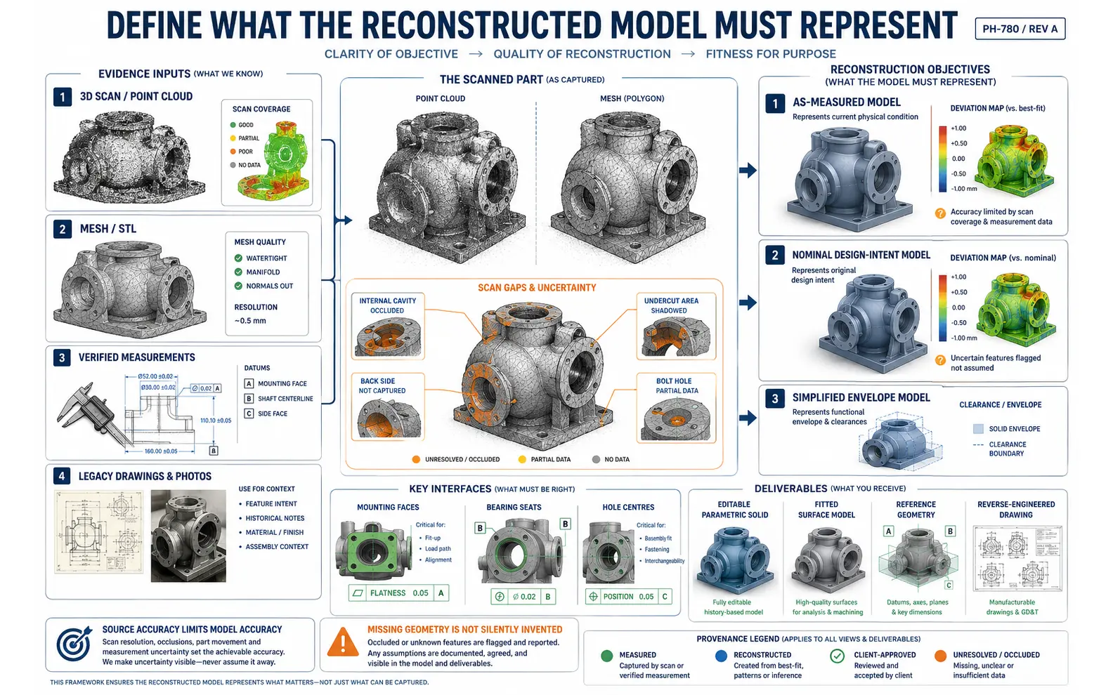
Start by Defining What the Reconstructed Model Must Represent
A worn replacement part may need a nominal model rather than a literal copy of its damaged surfaces. A cast housing may require machined interfaces to follow measurements while non-critical exterior faces are simplified. A supplier scan used for packaging clearance may need only an accurate envelope.
Our capabilities can include:
3D scan to CAD model development for mechanical parts and equipment
Physical part to CAD reconstruction using approved measurement sources
Mesh to SolidWorks conversion through direct reference or feature-based rebuilding
Legacy part reconstruction from samples, drawings and field information
Point cloud to mechanical CAD for suitable equipment and component datasets
STL to parametric model recreation where editability is required
Reverse engineered drawings based on approved reconstructed geometry
Measured component modeling using client or survey data
Scan data cleanup for alignment and reconstruction preparation
Replacement part CAD model production for client engineering validation
Manufacturing drawing reconstruction from reliable source evidence
The required accuracy must be stated in measurable terms and related to the available capture method. A visual enclosure model and a mating component have very different needs. We do not claim that a model is accurate beyond the resolution, coverage and reliability of the supplied data.
Understanding the Source before Building Geometry
Physical Samples and Manual Measurements
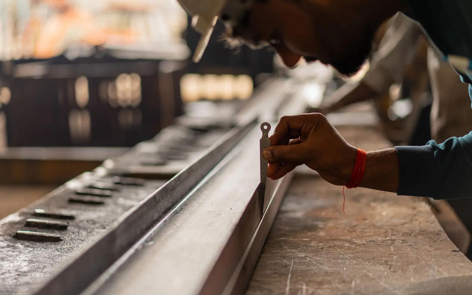
Physical part to CAD work may use callipers, micrometers, height gauges, coordinate measurements, photographs or client-prepared inspection sheets. The measurement method should match the component size, access and required accuracy.
We can organise and model from supplied values, but the client or appointed inspection provider remains responsible for equipment calibration, measurement technique and data validity. Conflicts between measurements are returned for confirmation.
Meshes and Polygonal Scan Data
STL, OBJ and other mesh files represent surfaces using polygons. Mesh to SolidWorks conversion can mean importing the mesh as a reference, fitting CAD surfaces or reconstructing a feature-based solid. These are different outputs with different editability.
Scan data cleanup may remove isolated polygons, close non-critical holes, align scan regions or reduce density for practical handling. Cleanup should not be mistaken for recovering geometry that was never captured.
Point Clouds
Point cloud to mechanical CAD can support larger equipment, fabricated systems and suitable industrial components. Before modeling, datasets may require registration, cropping, orientation and segmentation.
Occluded regions, reflective surfaces and inaccessible features can leave gaps. An expert modeler records where geometry follows measured points and where client-approved simplification has been used.
Reconstructing Nominal Design Intent
Scan surfaces often reflect manufactured variation rather than the original CAD definition. Cylinders may appear slightly irregular, planes may contain texture and symmetrical parts may not scan symmetrically. Rebuilding every deviation can create an unnecessarily complex model.
When the client requests nominal reconstruction, we identify likely primitive geometry, patterns, symmetry and feature relationships for review. The client approves which observed deviations represent wear or variation and which must be retained.
For legacy part reconstruction, older drawings, mating components, photographs and operating context may supplement the scan. These references can clarify a feature but may also conflict. A professional reconstruction keeps those conflicts visible rather than blending them into one undocumented interpretation.
Parametric versus Surface-Based Outputs
An STL to parametric model requires feature recreation. Sketches, planes, extrusions, revolves, patterns and holes are rebuilt around the agreed geometry so future dimensional changes are possible.
Freeform covers, castings and ergonomic shapes may require fitted surfaces instead. The scope should specify surface quality, continuity expectations, downstream use and whether a closed solid is required. Native feature history is delivered only when included and technically appropriate.
Deviation Review and Interface Control
Where requested, reconstructed CAD can be compared with the scan to visualise deviations. Colour maps or sectional comparisons may help the client identify areas of close fit and regions that require review.
A deviation plot does not automatically determine whether a part is acceptable. Thresholds, datum alignment, inspection method and functional consequences require engineering and quality decisions. We prepare the agreed comparison and return results to the authorised reviewers.
Interfaces deserve particular attention. Bearing seats, hole centres, mounting faces, sealing surfaces and mating envelopes may require higher-quality source data than exterior reference surfaces. An expert coordinator checks that interface queries and approved decisions remain connected to the affected features. A professional reviewer then verifies the final model and drawing references against the project register.
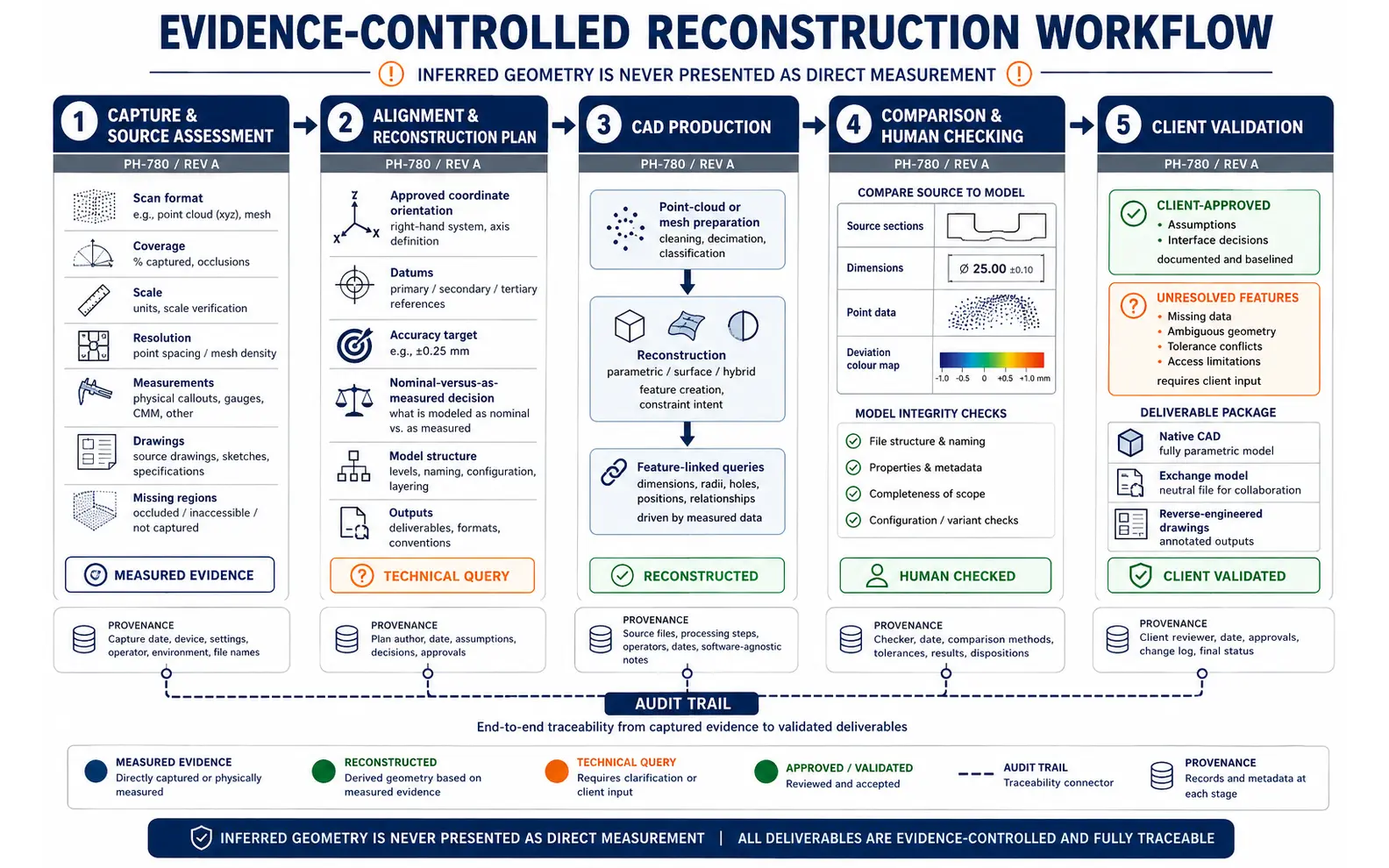
Our Reconstruction Workflow
Capture and Source Assessment
We review scan format, coverage, scale, resolution, measurements, available drawings and intended output. Missing or uncertain regions are identified.
Alignment and Reconstruction Plan
The client confirms coordinate orientation, datums, required accuracy, nominal-versus-as-measured treatment, model structure and deliverable formats.
CAD Production for Reverse Engineering and Scan-to-CAD
Mesh or point data is prepared, and authorised geometry is reconstructed using parametric, surface or hybrid methods. Queries remain linked to the relevant feature.
Comparison and Human Checking
Models are reviewed against source sections, dimensions, point data and approved requirements. File structure, properties and deliverable completeness are also checked.
Client Validation
The client reviews design-dependent assumptions, deviations and interfaces. Approved changes are incorporated before models and reverse engineered drawings are delivered.
This controlled process supports reverse engineering and scan to CAD outsourcing services without presenting inferred geometry as direct measurement.
AI Assistance in Data Classification and Feature Detection
AI-assisted tools may help classify scan regions, identify likely primitives, compare file metadata and prepare measurements or feature lists for human validation. These capabilities can accelerate preparation on suitable datasets.
AI does not decide whether a deviation is wear, choose a missing dimension or approve a reconstructed interface. Human modelers validate the geometry and client engineers resolve functional questions. This combination supports professional reverse engineering and scan to CAD services while keeping responsibility traceable.
Engagement Options for Reverse Engineering and Scan-to-CAD
One Critical Replacement Component
A single unavailable or obsolete part can be assessed using its physical sample, scans, measurements, mating information and any surviving drawings.
A Legacy Product Family
Companies can outsource reverse engineering and scan to CAD for a defined group of components that must be recovered, catalogued or migrated into a current CAD system.
Recurring Scan Reconstruction
Outsourced reverse engineering and scan to CAD support can process continuing field captures, service parts or customer-supplied scans. Stable intake and query procedures help maintain consistency.
As an expert reverse engineering and scan to CAD service provider, we recommend beginning with one representative component when capture quality or reconstruction expectations have not yet been established.
Offshore Reconstruction Support from India
We provide external-production reverse engineering and scan to CAD services for clients in the United States, Canada, European nations, the United Arab Emirates, Australia, South Africa, Singapore, Japan, Taiwan and India. Secure file exchange, dataset size, software versions and review times are agreed before production.
Some clients outsource the full reconstruction sequence; others delegate CAD production after a local metrology provider completes the capture. We work from the supplied evidence and clearly separate measured, reconstructed and client-approved information.
The appropriate reverse engineering and scan to CAD solution depends on source quality, geometry, required accuracy, model purpose and validation plan. Organisations comparing a reverse engineering and scan to CAD solutions company India can provide should assess reconstruction traceability and exception reporting alongside modeling capacity.
Reverse Engineering and Scan-to-CAD Project Case Studies
Project 1: Reconstructing an Obsolete Pump Impeller from Scan and Inspection Data
Project Name
Process Pump Impeller Reconstruction
Volume
One impeller, 14 scan regions and 38 verified inspection dimensions
Problem
A UAE process plant needed a CAD reference for an obsolete impeller. The available sample showed wear along blade edges, and the reflective surface had produced incomplete scan coverage near the hub.
Solution
We aligned the scan using client-approved datum surfaces, combined it with inspection dimensions and separated worn edges from confirmed geometry. Blade surfaces were reconstructed in stages and deviation views were submitted to the plant’s rotating-equipment engineer for approval.
Outcome
The client received a reviewed CAD model and drawing package for its own engineering, material and supplier-validation process.
Title
Rotating Equipment Engineer
Industry
Process Manufacturing
Country
United Arab Emirates
Project 2: Recovering Cast Machine Components for an Archive
Project Name
Textile Machine Casting Recovery
Volume
27 cast and machined components
Problem
An Indian textile-machinery builder had physical samples and fragmented paper drawings for an older product line. Cast exterior shapes were poorly documented, while machined interfaces needed reliable control.
Solution
The client’s metrology team supplied scans and verified interface measurements. We rebuilt machined features parametrically, used surface reconstruction for approved casting envelopes and maintained a source register showing which geometry came from drawings, measurements or scans.
Outcome
The manufacturer obtained an organised legacy model library that preserved evidence and supported its internal replacement-part review.
Title
Engineering Documentation Head
Industry
Textile Machinery
Country
India
Project 3: Recurring Scan-to-CAD Support for Custom Mobility Equipment
Project Name
Monthly Custom Interface Reconstruction
Volume
8–15 scanned brackets, mounts and interface parts per month
Problem
A Canadian mobility-equipment company captured customer-specific interfaces locally but had an irregular workload for turning approved scans into editable component models.
Solution
We established a recurring offshore intake package containing scan files, scale checks, orientation references and critical dimensions. Models were reconstructed in weekly groups, and missing regions were returned before finalisation.
Outcome
The client gained predictable CAD capacity while its engineers retained control of user safety, loading, fit, testing and release decisions.
Title
Adaptive Product Engineering Manager
Industry
Mobility Equipment
Country
Canada
Reverse Engineering and Scan-to-CAD Client Feedback
“
The worn and missing scan areas were not hidden. Each blade decision came back through a review image, which gave our engineer the control needed for this component.
Hassan R., Rotating Equipment Engineer, United Arab Emirates
“
The source register is particularly valuable. We can see which surfaces came from scans and which interfaces were governed by verified measurements.
Rohit V., Engineering Documentation Head, India
“
The intake checklist has made our recurring scans much more consistent. When coverage is inadequate, the team tells us before investing time in the final model.
Questions About Reverse Engineering and Scan-to-CAD
Can you create CAD from an STL or mesh file?+
Yes. The output may be a reference mesh, fitted surface, solid or reconstructed parametric model. The appropriate method depends on scan quality, geometry and required editability.
Do you perform the physical scanning?+
Our core service is CAD reconstruction from client- or provider-supplied scan and measurement data. Capture arrangements can be discussed separately, but coverage, accuracy and calibration responsibilities must be clearly assigned.
Can you recreate a worn replacement part?+
Potentially. The client must identify which wear or deformation should be corrected and approve the nominal geometry, critical interfaces, materials, tolerances and validation method.
How accurate will the reconstructed model be?+
Accuracy depends on capture resolution, coverage, calibration, alignment, geometry and review criteria. We agree measurable expectations after assessing representative data and do not claim precision unsupported by the source.
Let the Available Evidence Define the Reconstruction Plan
Send a representative scan, mesh, point cloud, measurement sheet or physical-part documentation together with the intended model use and accuracy requirements. We will assess the information and identify an appropriate reconstruction method.