Mechanical and SolidWorks Services / Technical Production
Part and Assembly Modeling Services for Connected Mechanical Systems
An individual component may be correct and still fail to support an effective assembly. File names can conflict, mates can break, purchased items can be duplicated, and subassemblies can become difficult to revise. Reliable assembly production therefore begins with a model hierarchy and reference strategy—not with placing every available part into one large file.
CAD Conversion Services India provides part and assembly modeling services for machinery, equipment, products, fixtures and fabricated systems. Our SolidWorks team creates components and organised assemblies from approved drawings, sketches, existing CAD data and client-issued engineering instructions.
We tailor the working method to the assembly’s purpose: documentation, interface review, exploded presentation, retrofit planning or preparation for client engineering analysis. Our external-production team produces the defined CAD package while design authority, calculations, tolerance decisions, performance validation and final release remain with the client’s authorised professionals.
✓ AI Powered✓ Free Pilot Batch✓ NDA Protected✓ 99.5% Quality
1500+Completed Projects
82%Returning Clients
10+Years Experience
45+Countries Served
35+Professionals Team
Project Fit at a Glance
Confirm these essentials before production begins.
Inputs
Sketches, legacy drawings, samples, measurements and approved engineering instructions
Outputs & deliverables
Parts, assemblies, production drawings, BOMs and agreed exchange files
Software
SolidWorks, AutoCAD and agreed mechanical CAD formats
Service intent
Focused production support for Part and Assembly Modeling, with scope, source authority and review responsibility agreed before work begins.
IndustriesArchitectureConstructionManufacturingEngineeringReal EstateCountries ServedUSACanadaUKAustraliaUAEEuropean Nations45+ Countries
IndustriesArchitectureConstructionManufacturingEngineeringReal EstateCountries ServedUSACanadaUKAustraliaUAEEuropean Nations45+ Countries
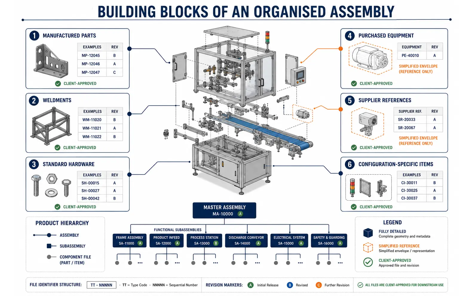
The Building Blocks of an Organised Assembly
A production assembly model may contain manufactured components, weldments, standard hardware, purchased equipment, supplier reference files and configuration-specific items. Each class may require different treatment to keep the model useful and maintainable.
Our scope can include:
3D part modeling from approved drawings and dimensional information
Mechanical assembly modeling for equipment and product structures
SolidWorks assembly services using client-approved standards
Component modeling for machined, fabricated, formed and moulded parts
Top-down assembly design support based on authorised layout geometry
Bottom-up assembly modeling from developed component files
Subassembly development for functional or manufacturing groups
Assembly interference checking as a defined CAD review activity
Parametric part creation for controlled revisions and product variants
Production assembly model preparation for agreed downstream uses
SLDPRT and SLDASM creation in the required SolidWorks version
The scope identifies which components must be fully detailed and which can remain simplified references. Purchased motors, bearings, fasteners or controls may not require native feature reconstruction when their purpose is only to establish an approved envelope or interface.
Choosing Between Bottom-Up and Top-Down Methods
Bottom-Up Assembly Modeling
Bottom-up assembly modeling begins with developed components that are brought together using agreed mates and positioning references. This approach is useful when parts already exist as controlled files or will be manufactured and released individually.
Before assembly, we check identifiers, units, coordinate orientation and revision status. Duplicate or conflicting components are reported. An expert modeler then applies the approved relationship method and organises parts into logical groups.
Top-Down Assembly Design Support
Top-down assembly design can use layout sketches, master geometry or in-context references to coordinate components around an overall arrangement. It may be suitable for equipment where interfaces and spatial relationships drive several parts.
This method must be governed carefully because uncontrolled external references can make components fragile or difficult to reuse. We follow client-approved reference rules and can break or preserve links as instructed. The engineering relationships themselves must be defined or approved by the client.
Hybrid Structures
Many practical assemblies use both approaches. Standard and independently released parts may be created bottom-up, while a controlled layout coordinates selected custom components. We document the chosen structure so future users understand which references are intentional.
Parametric Components within a Larger System
Parametric part creation can make approved variants easier to manage, but only when the driving relationships are known. We build features, dimensions and properties around the client’s supplied rules and expected change behaviour.
Component modeling may include configurations, patterned features, sheet-metal operations, weldments or simplified states. A professional reviewer checks that required part files resolve correctly and correspond with the issued drawing or dimensional source.
When several drafters contribute to the same product, an expert coordinator also reviews part numbers, file names, custom properties and assembly references across the package. This professional control reduces errors caused by inconsistent administration rather than geometry.
Subassemblies That Reflect Practical Ownership
Subassembly development can make a complex machine easier to navigate, revise and document. Groups may be organised around manufacturing responsibility, function, installation sequence, maintenance access or an existing product hierarchy.
We do not impose a generic subassembly structure. The client identifies how equipment is ordered, fabricated, assembled or serviced, and we translate that structure into the approved model hierarchy. Required flexible, rigid, simplified or configuration-specific subassembly behaviour is established during setup.
Bills of materials, exploded views and assembly drawings may be prepared where included. The file structure, item numbering and property mapping are checked together because an assembly can appear correct visually while producing an incorrect component list.
Assembly Checking within a Defined CAD Scope
Assembly interference checking can help identify overlapping solids, misplaced components or clear spatial conflicts. It is most useful when model completeness, component states and permitted contacts are defined in advance.
Not every detected contact is an error, and not every functional problem produces a visible clash. Fasteners, press fits, seals, weld preparations and intentionally overlapping reference geometry may require exclusions or client interpretation. Conversely, tolerance accumulation, flexible movement, thermal behaviour and manufacturing variation may create problems that a nominal CAD check cannot reveal.
We therefore report interference findings for engineering review rather than presenting them as automatic design approval. Clearance, motion and interface checks can be included when the client supplies the relevant criteria.
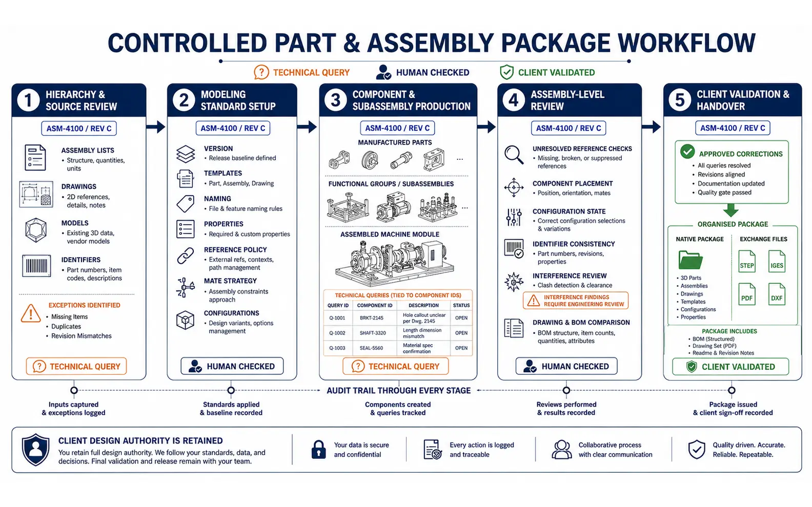
How We Build a Part and Assembly Package
Hierarchy and Source Review
We examine assembly lists, drawings, models, identifiers and required outputs. Missing components, duplicate references and uncertain revision states are logged.
Modeling Standard Setup
The team records SolidWorks version, templates, naming rules, properties, reference policy, mate strategy, configuration conventions and delivery structure.
Component and Subassembly Production
Parts and groups are created or organised in the approved sequence. Queries remain connected to the relevant component or interface.
Assembly-Level Review
The model is checked for unresolved references, component placement, configuration state, identifier consistency and requested interferences. Drawings and bills of materials are compared with the approved structure where included.
Client Validation and Handover
Engineering questions are resolved by the authorised client contact. Approved corrections are incorporated, and final native and exchange files are packaged together.
This workflow supports part and assembly modeling outsourcing services for both fixed machines and continuing product-development queues.
AI-Assisted Administration with Human CAD Review
AI-assisted tools may help classify component drawings, read title-block information, compare part lists, locate repeated identifiers and prepare properties for validation. These activities can reduce manual administration when assemblies contain many source files.
AI does not decide how a mechanism should move, define a missing interface or approve a product configuration. Human modelers verify the files, and client engineers resolve design-dependent questions. This division supports professional part and assembly modeling services without transferring engineering authority to automation.
Support Models for Different Assembly Workloads
One Defined Machine or Product
A complete assembly can be divided into components, subassemblies and review milestones. Early approval of the hierarchy reduces major restructuring near delivery.
Overflow Modeling Capacity
Companies can outsource part and assembly modeling when customer orders, redesigns or documentation deadlines create a temporary workload peak. Work packages can be assigned by module or component family.
Recurring Assembly Development
Outsourced part and assembly modeling support can cover regular component additions, approved revisions and product variants. A controlled intake list helps ensure every batch uses the current files.
As an expert part and assembly modeling service provider, we recommend supplying a product tree, bill of materials or representative assembly when available. These references help distinguish deliberate hierarchy from accidental file grouping.
Offshore Part and Assembly Support from India
We provide external-production part and assembly modeling services to clients in the United States, Canada, European nations, the United Arab Emirates, Australia, South Africa, Singapore, Japan, Taiwan and India. Software compatibility, file transfer, review windows and communication responsibilities are confirmed before modeling begins.
Some businesses outsource one equipment package; others delegate selected modules or recurring component updates. Our process keeps design decisions with the client and ensures that open questions remain visible during production.
The appropriate part and assembly modeling solution depends on source completeness, hierarchy, reference strategy, assembly size and intended deliverables. Organisations comparing a part and assembly modeling solutions company India can provide should examine how native files, relationships, exceptions and revision states will be controlled.
Part and Assembly Modeling Project Case Studies
Project 1: Structuring a Multi-Module Cartoning Machine Assembly
Project Name
Cartoning Equipment Assembly Reorganisation
Volume
326 parts, 21 subassemblies and one master machine assembly
Problem
A Spanish packaging-machine builder had valid component files but an unstable master assembly with duplicated hardware, inconsistent file paths and limited modular separation. Engineering teams found it difficult to isolate customer-specific stations.
Solution
The client defined its functional module structure, and we reorganised approved parts into controlled subassemblies. Purchased items were normalised to the agreed references, missing files were recorded and customer-specific modules were separated through approved configurations.
Outcome
The resulting hierarchy was easier for the client to navigate, review and use as the basis for module-level drawing updates.
Title
Mechanical Systems Manager
Industry
Packaging Machinery
Country
Spain
Project 2: Modeling a Fabricated Test Rig from Released Drawings
Project Name
Hydraulic Component Test Stand Model
Volume
54 fabricated and machined parts, 9 purchased items and 6 subassemblies
Problem
A UAE industrial-services company had approved fabrication drawings for a test stand but needed a coordinated assembly for installation planning and client presentation. Several supplier files used different coordinate orientations.
Solution
We modeled the released custom components, simplified the supplied equipment files and established a consistent assembly origin. Interference findings were issued as review items, allowing the client’s engineer to confirm intentional contacts and revise two interfaces.
Outcome
The company received an organised assembly and exploded presentation suitable for its defined planning and documentation needs.
Title
Workshop Engineering Manager
Industry
Industrial Testing Equipment
Country
United Arab Emirates
Project 3: Recurring Subassembly Support for Agricultural Implements
Project Name
Monthly Implement Module Modeling
Volume
10–18 parts and 2–4 subassemblies per month
Problem
A Taiwanese agricultural-equipment manufacturer regularly introduced market-specific brackets, guards and mounting modules. Its internal team needed flexible CAD capacity without changing its engineering-release process.
Solution
We established a recurring offshore work queue linked to approved drawings and part lists. Each module was modeled, assembled and checked against the current product configuration before a review package was issued.
Outcome
The manufacturer gained steady production support while its engineers continued to control interfaces, testing and final product approval.
Title
Product Development Supervisor
Industry
Agricultural Equipment
Country
Taiwan
Part and Assembly Modeling Client Feedback
“
The new hierarchy reflects how we actually divide the machine into customer modules. Missing references and duplicates were documented clearly during the reorganisation.
Carlos V., Mechanical Systems Manager, Spain
“
The assembly gave our workshop and project teams a common visual reference. Interference results came back as review questions, which was the correct approach for our equipment.
Omar K., Workshop Engineering Manager, United Arab Emirates
“
Recurring module support now fits into our existing release system. The files follow our product structure, and our engineers remain responsible for every technical decision.
Chien-Hao L., Product Development Supervisor, Taiwan
Questions About Part and Assembly Modeling
Can you work with existing SolidWorks parts and assemblies?+
Yes. We can assess existing native files, imported geometry and related drawings. Missing references, incompatible versions and unclear revision states should be resolved during setup.
Do you perform assembly interference checks?+
Yes, when included in scope. Results depend on model completeness and approved exclusion criteria. Findings are submitted for client engineering review rather than treated as automatic design approval.
Can you organise large assemblies into subassemblies?+
Yes. The hierarchy should reflect the client’s functional, manufacturing, installation or maintenance structure. We can implement the approved organisation and update related references.
Do you create the bill of materials?+
We can prepare or configure model-linked bills of materials using approved part numbers, quantities and properties. Commercial, material and engineering information must be supplied or validated by the client.
Give Every Component a Controlled Place in the Assembly
Share a representative assembly, drawing package, part list or product hierarchy together with the required SolidWorks version and intended deliverables. We will review the information and define an appropriate modeling and checking workflow.