Reinforced and Precast Concrete Detailing Services for Production and Assembly
Concrete components pass through design, detailing, casting and installation. Reinforcement, embeds, mould geometry, transport limits and erection interfaces must agree for elements to fit on site.
Our reinforced and precast concrete detailing services convert approved engineering and supplier information into coordinated drawings, schedules and models. CAD Conversion Services India works with precast manufacturers, concrete contractors, engineering consultancies and construction teams using AutoCAD and Revit.
Production assistance does not replace structural design. Qualified project professionals must approve reinforcement, connections, lifting requirements and other engineering decisions.
✓ AI Powered✓ Free Pilot Batch✓ NDA Protected✓ 99.5% Quality
1500+Completed Projects
82%Returning Clients
10+Years Experience
45+Countries Served
35+Professionals Team
Project Fit at a Glance
Confirm these essentials before production begins.
Inputs
Engineer-issued design information, calculations, mark-ups and project standards
Outputs & deliverables
Structural models, drawings, schedules and material-specific detailing
Software
AutoCAD, Revit and agreed structural-production tools
Service intent
Focused production support for Reinforced and Precast Concrete Detailing, with scope, source authority and review responsibility agreed before work begins.
IndustriesArchitectureConstructionManufacturingEngineeringReal EstateCountries ServedUSACanadaUKAustraliaUAEEuropean Nations45+ Countries
IndustriesArchitectureConstructionManufacturingEngineeringReal EstateCountries ServedUSACanadaUKAustraliaUAEEuropean Nations45+ Countries
One Concrete Structure, Several Production Responsibilities
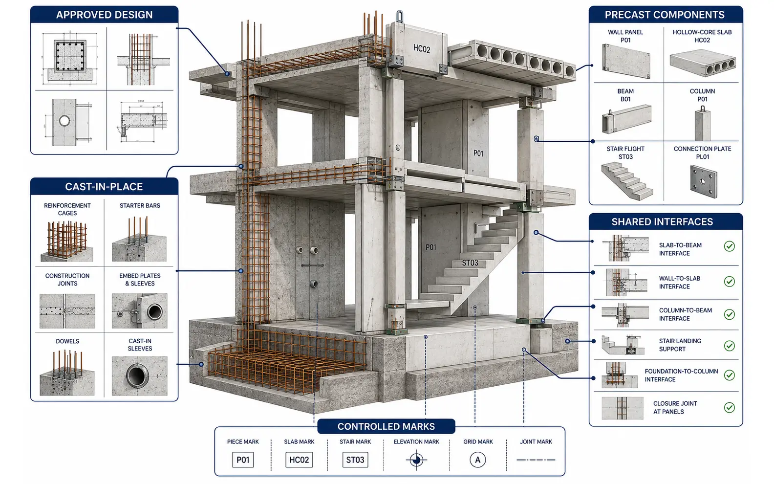
Cast-in-place and precast methods differ, but both depend on accurate interfaces. Panels, slabs, starter bars, embeds and tolerances must follow approved structural and architectural requirements.
Before detailing, we establish:
Authoritative structural and architectural drawings
Approved component and reinforcement design
Concrete grades, cover and durability requirements
Precast supplier standards and mould constraints
Connection, embed and bearing information
Element marking and schedule conventions
Transport, lifting and erection data supplied by the client
Construction joints and approved pour sequences
Required models, drawings and exchange files
Review status and authorised technical contacts
This responsibility map gives the project a reinforced and precast concrete detailing solution based on the actual production route rather than a generic component library.
Reinforced Concrete Details for Site Construction
Reinforced concrete detailing may cover foundations, walls, columns, beams, slabs, stairs and other cast-in-place elements. Drawings can communicate approved geometry, reinforcement, joints, openings and embedded items through plans, sections and schedules.
Typical work packages include:
Foundation and retaining-wall details
Column, wall and core reinforcement
Beam and column detailing at frame intersections
Flat-slab and transfer-slab zones
Stair and slab detailing
Pits, plinths and equipment foundations
Opening and embed coordination
Concrete joint details
Approved reinforcement and material schedules
Where bars, sleeves or cast-in items appear congested, the condition is documented for engineering and construction review. The detailer does not reduce reinforcement, move a structural opening or alter an embed merely to make the drawing appear cleaner.
Precast Component and Panel Drawings
Precast shop drawings organise approved component geometry, reinforcement, embeds, finishes and interfaces for manufacturing review. Each piece must be identifiable, schedulable and connected to the correct project location.
Precast Panel Drawings
Precast panel drawings can include elevations, sections, edge profiles, openings, reinforcement, inserts, connection plates and surface references. Panel marks are coordinated with layouts and schedules so visually similar pieces are not treated as interchangeable without verification.
Double Wall Panel Drawings
Double wall panel drawings may document inner and outer wythes, lattice or connecting reinforcement, voids, joint geometry, openings, embeds and cast-in-place interfaces. The model and drawings follow the manufacturer’s approved system and engineering information.
Hollow Core Slab Detailing
Hollow core slab detailing can cover unit layouts, marks, lengths, bearings, openings, approved notches, topping interfaces and support conditions. Unit design and permitted field modifications remain subject to the precast engineer or supplier.
Stairs, Beams, Columns and Repetitive Elements
Precast stairs, beams and columns often repeat in general form while differing at landings, supports, embeds or connection zones. A controlled type and mark system helps separate true repetitions from project-specific variations.
We can prepare:
Component arrangements and setting-out plans
Individual element elevations and sections
Approved reinforcement layouts
Bearing and interface details
Embed, plate and insert information
Lifting references supplied by the responsible engineer
Piece schedules and material summaries
Revision registers linked to element marks
An experienced checker compares component drawings with arrangement plans and schedules. If a change affects one element family, the review identifies every related mark rather than assuming that copied details updated correctly.
Connections, Joints and Embedded Items
Precast performance depends on component and support interfaces. Concrete joint details may show approved gaps, bearings, dowels, plates, welds, bolts or closure-pour reinforcement.
Coordination can address:
Panel-to-panel and panel-to-frame interfaces
Beam, column and corbel bearings
Slab units at walls, beams and openings
Cast-in plates and connection hardware
Façade support and waterproofing zones
Starter bars and closure reinforcement
Service penetrations and embedded conduits
Construction and erection tolerances supplied by the client
Connection engineering, temporary conditions and lifting design are included only under an expressly authorised scope with qualified review. A production drawing cannot establish capacity simply by showing a plate or insert.
Reinforcement Schedules and Bar Information
Concrete reinforcement schedules can consolidate bar marks, sizes, shapes, lengths, quantities and element references from the approved detail set. Their structure may follow the contractor’s, fabricator’s or national scheduling standard.
Schedule checking includes drawing-callout agreement, bar geometry, repetition, component references and revision status. Quantities may support production planning, but allowances for waste, stock length, offcut reuse and purchasing are applied only when defined by the client.
For precast components, reinforcement schedules remain tied to the piece or family mark. This prevents an updated panel design from silently changing reinforcement assigned to an earlier mould release.
Revit Precast Modeling for Coordinated Documentation
Revit precast modeling can provide a controlled source for component geometry, marks, views and schedules. The model may include panels, columns, beams, stairs, slabs, embeds and approved connection elements according to the required level of information.
Model-based production can support:
Component arrangements and three-dimensional review
Shop-drawing plans, elevations and sections
Piece marks and schedules
Interface and embed coordination
Approved quantity extraction
Erection views and model exchanges
Revision comparison by component or zone
A qualified modeler checks coordinates, levels, families, parameters, joins, marks, warnings and drawing views. AI-assisted comparison may help identify duplicate marks or revision differences, but acceptance remains a human responsibility.
Precast Erection Drawings with Clear Status
Precast erection drawings can show grids, levels, component marks, orientation, bearing locations, approved field connections and installation references. Releases may be organised by building zone, floor, crane sequence or client-defined milestone.
The drawings document approved erection information supplied by the responsible team. Crane selection, lifting procedures, temporary bracing, stability calculations, site sequencing and safety remain with the contractor and qualified engineers unless separately assigned.
Issue status is kept visible. A drawing submitted for coordination is not labelled as released for erection until the authorised party confirms that status.
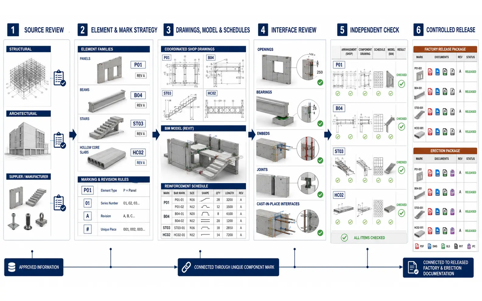
A Production Workflow Connected to Component Marks
Source and System Review
We register structural, architectural, supplier and connection information. Precast-system requirements and cast-in-place interfaces are identified.
Element and Mark Strategy
Component types, unique pieces, model parameters, drawing numbers and revision conventions are established. A sample piece can be completed first.
Drawings, Models and Schedules
Detailers develop approved geometry, reinforcement, embeds, views and schedules while maintaining references to the controlling sources.
Interface and Constructability Review
Openings, joints, bearings, connections and congested zones are checked. Conditions requiring design or site judgement are returned to authorised reviewers.
Independent Checking for Reinforced and Precast Concrete Detailing
An experienced reviewer compares arrangements, components, marks, reinforcement, embeds, schedules and model outputs. Automated tools assist with comparison but do not approve changes.
Controlled Release
Deliverables are issued by agreed production or erection priority. Approved comments are applied to all affected elements and rechecked.
Deliverables That Can Match the Manufacturer’s System
Depending on scope, deliverables may include:
Cast-in-place reinforcement details
Precast shop drawings and piece drawings
Panel, beam, column and stair documentation
Slab and double-wall layouts
Connection and embed details from approved designs
Reinforcement and component schedules
Precast erection drawings
Revit models and coordination views
DWG, PDF, RVT, IFC and agreed schedule files
Templates, notation and software versions are confirmed during setup. Native-model delivery does not remove the need for checked PDFs or other review documents where the client requires them.
Offshore Concrete Detailing for Variable Production Loads
Our offshore reinforced and precast concrete detailing services can support a fixed building package, a manufacturer’s production peak or recurring releases across several projects.
Clients may assign externally reinforced and precast concrete detailing when internal teams need additional drawing or model capacity. Reinforced and precast concrete detailing outsourcing services can also provide recurring help through outsourced reinforced and precast concrete detailing support.
As an experienced reinforced and precast concrete detailing service provider, we maintain component marks, drawing status and unresolved queries. Our qualified reinforced and precast concrete detailing services remain tied to approved engineering and manufacturing information.
The offshore team follows the client’s communication and document-control environment instead of creating an isolated production record.
Reinforced and Precast Concrete Detailing Project Case Studies
Project 1: Precast Envelope Package for a University Laboratory
Volume
382 insulated panels with 54 unique opening and support conditions
Problem
A Canadian precast manufacturer received architectural elevations, structural support drawings and laboratory-service penetration data on different revision cycles. Repeated panel types were becoming increasingly difficult to distinguish from local exceptions.
Solution
We created a panel-family register and linked every piece to its support, opening and finish status. Standard panels shared controlled types, while exceptional pieces received unique marks and enlarged interface views. Approved structural and architectural changes were mapped to affected marks before each mould release.
Outcome
The manufacturer could sequence production using reliable piece schedules while keeping local variations visible. Later penetration changes were directed to the relevant panels instead of triggering a manual review of the complete façade.
Title
Precast Design Manager
Industry
Education and Research Construction
Country
Canada
Project 2: Reinforced-Concrete Details for an Underground Station
Volume
96 wall pours, 28 major openings and 1,260 reinforcement callouts
Problem
A Singapore civil contractor needed reinforcement documentation for station walls whose service openings and embedded plates continued to change during coordination. The construction team required pour-specific releases without losing continuity across adjacent wall zones.
Solution
We divided the approved concrete and reinforcement information by pour, maintained interface sections at every boundary and tracked embeds through a separate register. Congested openings were modeled for visual review, while any reinforcement modification remained subject to the structural engineer’s approval.
Outcome
Site releases aligned with the contractor’s pour plan, and bars continuing across boundaries remained traceable. Embed changes could be coordinated before the affected wall package reached construction.
Title
Civil Structures Manager
Industry
Rail Infrastructure
Country
Singapore
Project 3: Recurring Detailing for a Precast Housing Manufacturer
Volume
70–110 component drawings and schedules per month
Problem
An Australian manufacturer adapted standard wall, stair and balcony components for multiple housing developments. Internal staff needed flexible help with approved project variations but could not allow client-specific details to alter the standard library.
Solution
We separated controlled master families from project copies and used change sheets authorised by the manufacturer’s engineers. A consistent checking lead reviewed marks, reinforcement, embeds and schedule updates before each submission. Unapproved deviations remained quarantined from the masters.
Outcome
The manufacturer gained predictable production capacity while protecting its standard component data. Project-specific revisions remained traceable, and repeated developments required less setup.
Title
Product Engineering Lead
Industry
Precast Housing Manufacturing
Country
Australia
Reinforced and Precast Concrete Detailing Client Feedback
“
The panel-family register made every exception visible without making the standard pieces harder to manage. It became much easier to plan mould releases.
Samantha R., Precast Design Manager, Canada
“
The pour-boundary sections were clear and the embed register gave our coordination team a practical way to manage late service changes.
Farhan I., Civil Structures Manager, Singapore
“
Their recurring support protects our master components while handling approved project variations efficiently. That distinction is essential for our production system.
Matthew J., Product Engineering Lead, Australia
Questions About Reinforced and Precast Concrete Detailing
Can you design precast connections or lifting systems?+
These activities require qualified engineering and must be separately scoped with confirmed loads, standards and approval responsibilities. Our standard detailing service represents connection and lifting information supplied or approved by the responsible engineers.
Can you follow our existing precast component library?+
Yes. We first review family structure, marks, parameters, drawings and revision conventions. Project copies can be separated from controlled master content so approved variations do not affect other work.
Do you prepare reinforcement schedules for cast-in-place concrete?+
Yes, when approved reinforcement information and the required scheduling standard are available. Bars remain cross-referenced to drawings, elements and revisions so the schedules can be checked.
Can you revise a package after production has started?+
Yes, but the client must identify component status and what has already been cast or procured. We assess affected marks, drawings and schedules so revisions are not applied indiscriminately to completed work.
Send a Representative Component and Its Interfaces
Share approved structural information, supplier standards, component examples, connection references, required outputs and production priorities. We will identify gaps and recommend a practical qualified workflow.
Whether you want to assign externally one component package or add recurring offshore capacity, the model, drawings and schedules should follow one controlled mark system.