MEP and Electrical Services / Technical Production

HVAC Drafting and BIM Modeling Services for Buildable Documentation

HVAC information changes form during a project. Consultants issue calculations and layouts, contractors develop coordinated routes, and site teams record approved changes. Each stage needs a reliable connection to the engineering basis.

Mechanical consultants and contractors use our HVAC drafting and BIM modeling service when approved design information must become coordinated duct, pipe and equipment documentation. AutoCAD supports precise 2D issue sets, while Revit supports spatial review, schedules and model-based sheets.

Our external-production role is production-focused. Airflow calculations, thermal loads, equipment selection, duct and pipe sizing, pressure-loss analysis, controls, acoustic requirements, insulation, support engineering, code compliance and final release remain with the client’s authorised mechanical engineer.

Companies can outsource HVAC drafting and BIM modeling when they need scalable documentation capacity without transferring design responsibility. AI-assisted comparisons may support revision review or clash classification, while a human expert controls the delivered output.
✓ AI Powered✓ Free Pilot Batch✓ NDA Protected✓ 99.5% Quality
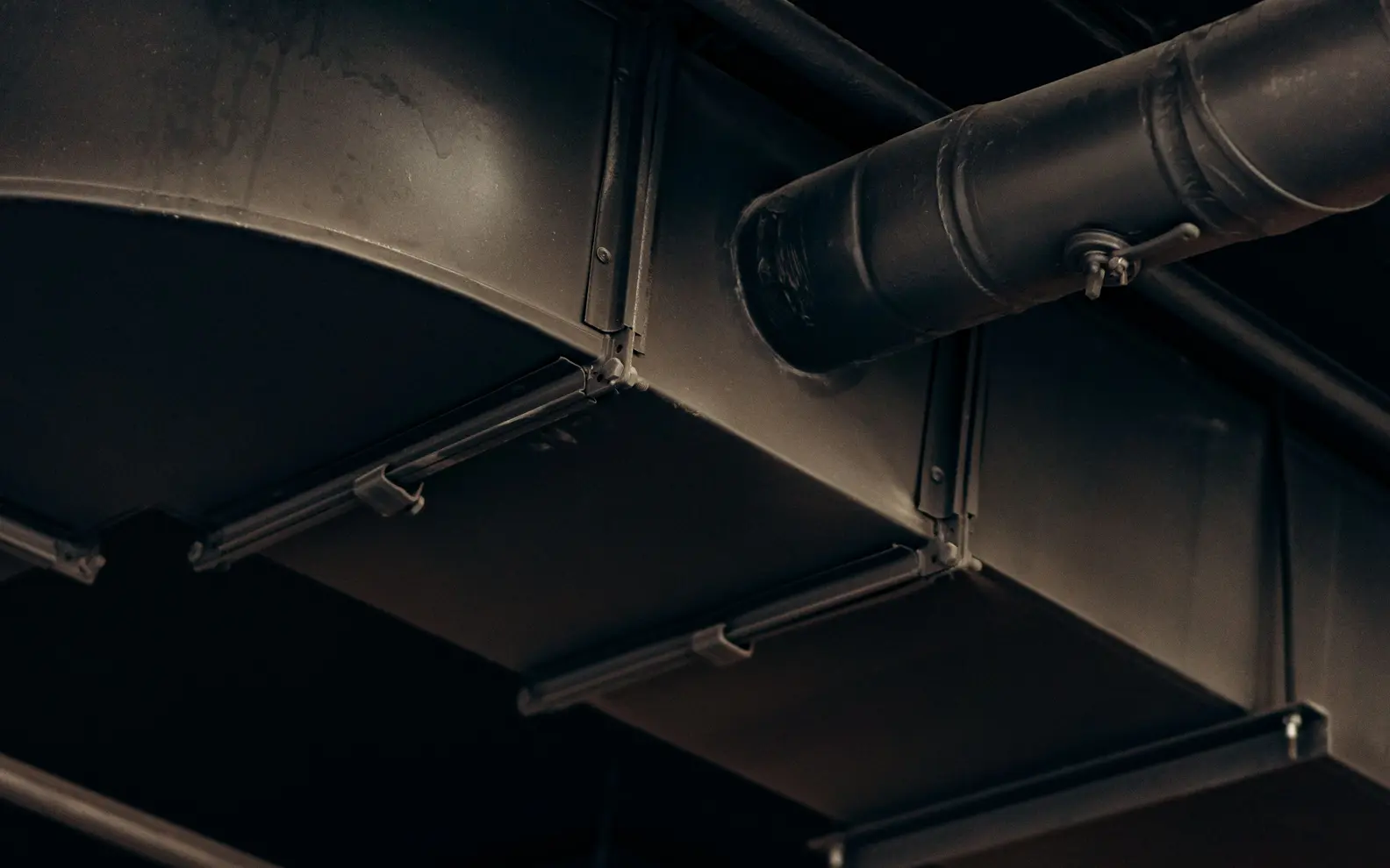
Detailed overhead HVAC air-duct installation inside a modern commercial building
Commercial HVAC coordination
1500+Completed Projects
82%Returning Clients
10+Years Experience
45+Countries Served
35+Professionals Team

Project Fit at a Glance

Confirm these essentials before production begins.

Inputs

Approved discipline designs, equipment data, backgrounds and coordination standards

Outputs & deliverables

MEP drawings, models, schedules, coordination views and record updates

Software

AutoCAD, Revit and approved review tools

Service intent

Focused production support for HVAC Drafting and BIM Modeling, with scope, source authority and review responsibility agreed before work begins.

IndustriesArchitectureConstructionManufacturingEngineeringReal EstateCountries ServedUSACanadaUKAustraliaUAEEuropean Nations45+ Countries

HVAC Documentation Must Reflect the Project Stage

A design-intent drawing, coordination model and fabrication package should not be treated as the same deliverable. The required geometry, annotations, tolerances and product information change as a project advances.

Our scope can include:

  • HVAC CAD drafting from approved engineering mark-ups
  • Revit HVAC modeling for coordinated building-services delivery
  • Ductwork BIM modeling using accepted sizes and elevations
  • Mechanical equipment modeling from approved schedules or product data
  • Chilled water piping model development for authorised routes
  • HVAC shop drawings for contractor and consultant review
  • Duct layout drawings for supply, return, exhaust and ventilation systems
  • HVAC coordination drawings showing accepted service relationships
  • HVAC clash detection and issue documentation
  • LOD HVAC model production to defined project requirements
  • Ventilation system drafting for approved layouts
  • Drawing revisions, record updates and as-built model support

Use is agreed before production. Coordination geometry should not support fabrication or procurement unless that information level has been included and approved.

Inputs That Define the Mechanical Production Basis

We review the production basis, not only the drawing count. A reliable brief identifies:

  • Approved mechanical design layouts and calculations
  • Equipment and terminal schedules
  • Duct and pipe sizes, levels and routing criteria
  • Architectural, structural and other service references
  • Required AutoCAD or Revit version
  • Project coordinates, grids and levels
  • Drawing templates, symbols and annotation standards
  • Model worksets, families, parameters and classification rules
  • LOD, coordination tolerance and permitted model use
  • Shop-drawing or submission requirements
  • Query, review and approval responsibilities

When different sources conflict, we record the location and affected system. The appointed mechanical engineer or contractor decides which instruction governs.

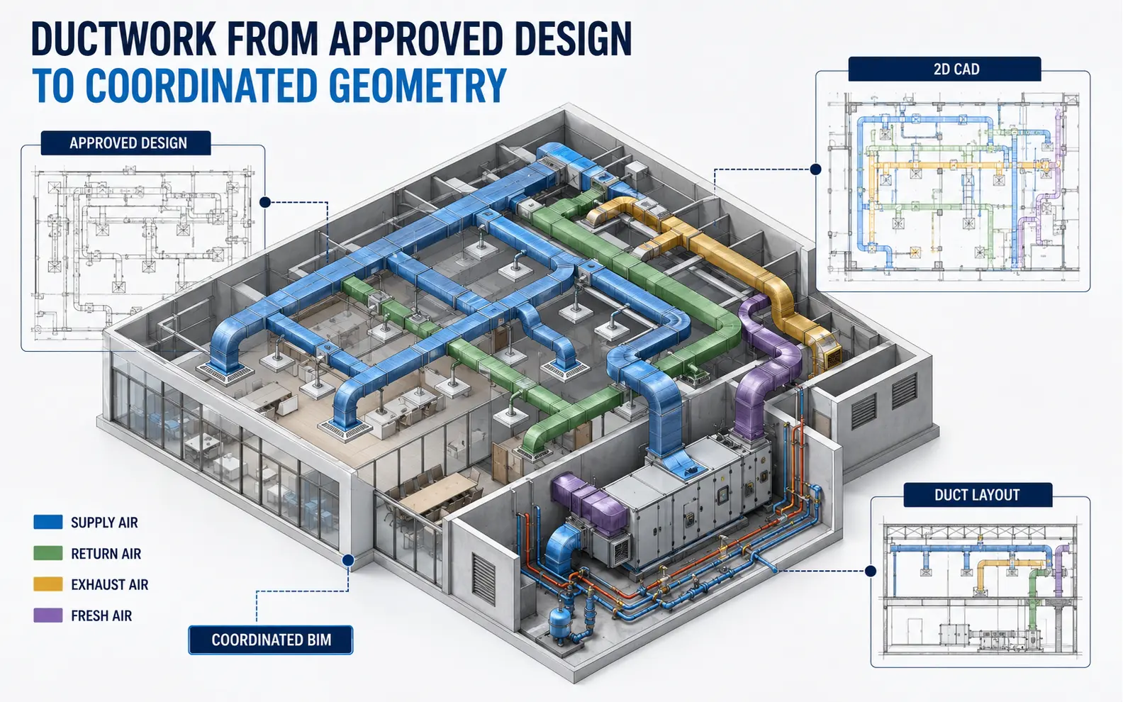
Ductwork from Approved Design to Coordinated Geometry

Coordinated HVAC model connecting approved design drawings with supply, return, exhaust and fresh-air duct layouts
Approved engineering information is translated into controlled CAD drawings and coordinated duct, equipment and hydronic-system geometry.

HVAC CAD Drafting

HVAC CAD drafting can cover plans, schematics, risers, sections, details and equipment schedules. We follow client layers, title blocks, symbols, lineweights and plotting standards. Approved mark-ups are incorporated through controlled revisions.

Two-dimensional work is often appropriate for design submissions, tender packages, smaller projects and legacy updates. Xrefs and backgrounds are managed so architectural changes remain traceable.

Ductwork BIM Modeling

Ductwork BIM modeling represents approved supply, return, exhaust, fresh-air and other systems in coordinated space. Sizes, elevations and routing are taken from the accepted design or authorised coordination instructions.

Fittings, transitions, dampers, terminal connections and accessories can be modeled at the agreed detail. CCSI does not select duct sizes, calculate pressure loss or determine fire and smoke-control requirements.

Duct Layout Drawings

Duct layout drawings communicate route, size, level, system and connection information at an appropriate scale. Sections and enlarged views can clarify congested ceiling zones, risers and plant areas.

The drawings may be created in AutoCAD or derived from Revit, depending on the project workflow. Notes and installation information are included only from approved sources.

Equipment and Hydronic-System Modeling

Mechanical Equipment Modeling

Mechanical equipment modeling may include air-handling units, fans, pumps, chillers, terminal units and other approved items. Manufacturer content can be used where it meets project requirements; otherwise, a controlled representation may be prepared for client review.

Connection locations, service zones and parameters are based on authorised schedules and product information. Performance, access and maintenance requirements remain subject to engineering and supplier confirmation.

Chilled Water Piping Model

A chilled water piping model can show approved flow and return routes, branches, valves and equipment connections. Pipe sizes, gradients where relevant, insulation allowances and clearance criteria must be provided or approved by the client.

Where fabrication detail is requested, the scope should define joints, valves, supports, sleeves, spool boundaries and required data. A coordination-level pipe is not automatically a fabrication-ready system.

Plant Rooms and Service Zones

Plant rooms often combine equipment, ductwork, pipework, containment, drainage and structural constraints. Focused models, sections and maintenance-zone graphics help project teams evaluate approved arrangements.

We identify visible spatial concerns but do not approve access, lifting routes, equipment replacement strategy or safe maintenance provisions.

HVAC Coordination and Clash Review

HVAC coordination drawings and models bring the mechanical system together with accepted architectural, structural, electrical, plumbing and fire-protection references. Coordination may examine ceiling zones, shafts, risers, plant rooms, corridors and penetrations.

HVAC clash detection uses agreed rules to locate intersections and proximity issues. Automated results require review because some clashes are duplicates or depend on discipline priority.

We can prepare viewpoints, issue descriptions and status registers for project-team meetings. The client’s consultants and contractors decide route changes, clearances, system priority and technical acceptability. Approved decisions are incorporated into the next model or drawing issue.

HVAC Shop and Coordination Drawings

HVAC shop drawings can include coordinated duct and pipe plans, sections, elevations, plant-room details, equipment connections, sleeve references and installation notes from approved contractor information.

HVAC shop drawings are submitted through the contractor’s and consultant’s review route. CCSI prepares the documentation but does not authorise fabrication, installation or commissioning.

HVAC coordination drawings may use simplified graphics for multidisciplinary review, while installation sheets may require greater detail. We avoid assuming that one view type satisfies both purposes.

Managing LOD Without Unnecessary Model Weight

An LOD HVAC model should represent the project’s actual information need. Overly detailed families can slow coordination while adding little value; simplified geometry can become misleading if critical dimensions are omitted.

We agree:

  • Systems and zones included in the model
  • Required equipment geometry and parameters
  • Duct and pipe fitting representation
  • Insulation and clearance display requirements
  • Accessory, damper, valve and terminal detail
  • Hanger, support and sleeve inclusion
  • Required drawing and schedule outputs
  • Information required for coordination, fabrication or handover

This creates an auditable modeling instruction and reduces inconsistent assumptions between team members.

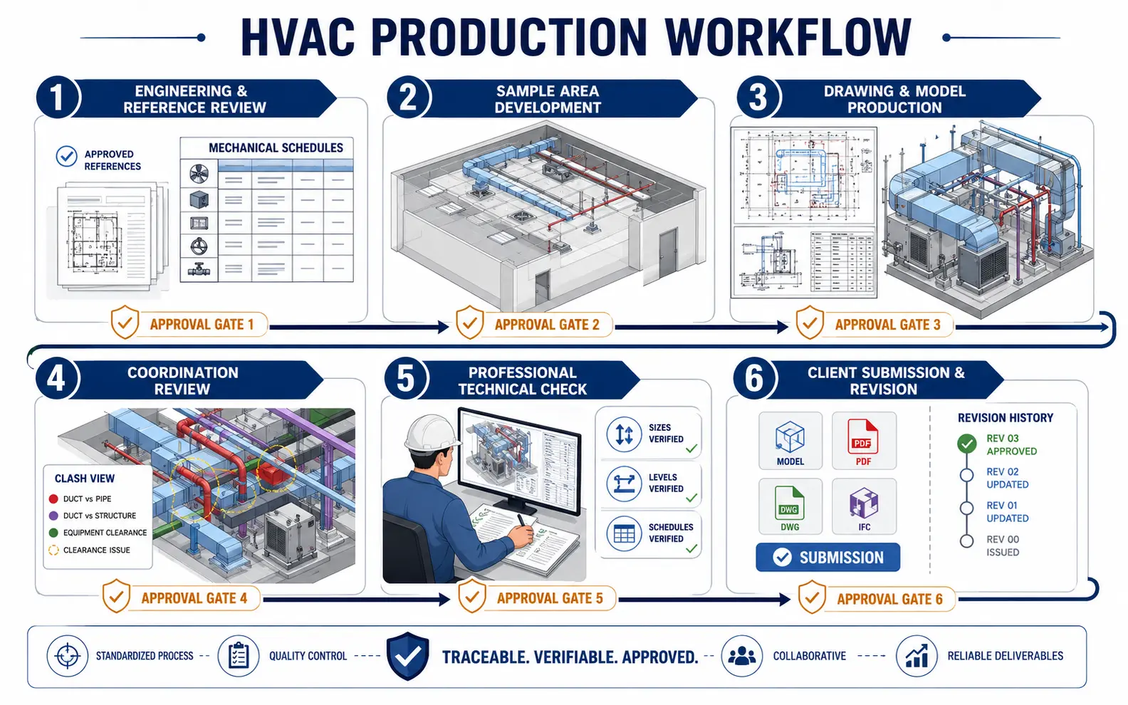
Our HVAC Production Workflow

Six-stage HVAC production workflow covering reference review, sample development, modeling, coordination, technical checking and revision-controlled submission
Reference status, sample approval, production, clash review, professional checking and client-authorised revisions remain traceable throughout delivery.

1. Engineering and Reference Review

We identify the approved mechanical design basis, current building references, equipment data, deliverables and model standards. Missing sizes, elevations or technical instructions become queries.

2. Sample Area Development

A typical zone, plant area or sheet is prepared first. The client confirms drafting style, element detail, family use, annotations and expected presentation.

3. Drawing and Model Production

Approved ductwork, piping and equipment information is developed in AutoCAD or Revit. File structure, systems, worksets and revision references follow the project requirements.

4. Coordination Review

HVAC coordination checks compare ducts, pipes and equipment access requirements with the current architectural, structural and services backgrounds. Observations are grouped by location for the consultant’s decision.

5. Professional Technical Check

The HVAC reviewer traces major routes from source to output, checks plant and terminal references, inspects levels and sizes, and confirms the required views and schedules are present. Automation may highlight differences, but a human signs off the production check.

6. Client Submission and Revision

Files are issued at agreed milestones. Review comments and approved coordination outcomes are recorded and applied. The client authorises the final project use.

Quality Controls Around the HVAC Package

Depending on scope, checks may cover:

  • Coordinates, levels, grids and reference alignment
  • Use of the latest accepted architectural background
  • Duct and pipe sizes against supplied design information
  • Route continuity and connected fittings
  • Equipment identifiers and schedule references
  • Layers, systems, worksets, families and naming rules
  • Approved clash resolutions and issue status
  • Sections, details, annotations and sheet references
  • Required native files, links and exports
  • Comment incorporation and revision identification

These checks assess documentation and model consistency. They do not validate thermal performance, airflow, hydronic calculations, equipment capacity, controls, fire strategy, acoustic design or regulatory compliance.

This boundary is central to our HVAC drafting and BIM modeling solution.

Engagement Models for HVAC Drafting and BIM Modeling

Fixed Design-Documentation Package

A defined drawing or model scope can align with a concept, design-development, tender, coordination or construction milestone.

Contractor Production Support

Contractors may use additional resources for coordination updates, HVAC shop drawings and comment incorporation within their existing review process.

Legacy Conversion and Model Recovery

Approved 2D drawings, scans or older models can be rebuilt to a consistent CAD or Revit structure. Source quality determines achievable accuracy.

Recurring Project Capacity for HVAC Drafting and BIM Modeling

external-production HVAC drafting and BIM modeling services can support project portfolios through scheduled work packages. Shared standards and a named coordinator improve continuity while design authority stays with each project’s engineers.

Why Outsource HVAC Production?

Mechanical documentation workloads fluctuate around design submissions, clash-review cycles and construction releases. External capacity can keep production moving while internal engineers focus on calculations, coordination decisions and project leadership.

HVAC support can be scoped around a plantroom, floor, building or recurring sequence of consultant-approved updates. CCSI supplies additional drawing and model capacity while the mechanical engineer controls loads, equipment selection, sizing and final release.

Professional HVAC drafting and BIM modeling services are most effective when approved inputs, intended model use, query ownership and acceptance criteria are defined before work begins.

HVAC Drafting and BIM Modeling Project Case Studies

Pharmaceutical Plant HVAC Coordination Package

Project Name
Pharmaceutical Plant HVAC Coordination Package
Volume
21,400 m² facility and 11 coordinated model zones
Problem
A German engineering contractor had approved airflow calculations and system layouts, but ceiling zones contained dense process, electrical and fire-protection services. Mechanical routes required structured coordination before shop documentation.
Solution
Our offshore team developed the accepted duct and chilled-water geometry, organised clashes by zone and prepared sections around congested areas. Contractor and consultant engineers approved route changes, clearances and system priorities.
Outcome
Coordination meetings used clearer mechanical references, and approved decisions transferred consistently into the next drawing package.
Title
Mechanical BIM Coordination Lead
Industry
Pharmaceutical Facilities
Country
Germany

Hotel Ventilation Drawing Recovery

Project Name
Hotel Ventilation Drawing Recovery
Volume
186 legacy drawings across 2 connected towers
Problem
A South African hotel operator held scanned ventilation drawings, later renovation mark-ups and incomplete CAD files. The archive was difficult to use for engineer-led refurbishment planning.
Solution
The client chose to outsource HVAC drafting and BIM modeling recovery for selected floors. We redrew accepted layouts, built representative Revit zones and logged unreadable sizes or conflicting routes for engineer review. A professional checker compared each output with its stated source.
Outcome
The operator received an organised reference baseline without presenting historical layouts as verified current conditions.
Title
Technical Facilities Manager
Industry
Hospitality
Country
South Africa

Recurring Retail HVAC Submission Support

Project Name
Recurring Retail HVAC Submission Support
Volume
7–10 store packages per month
Problem
An Australian mechanical contractor managed frequent retail fit-outs with changing tenancy plans, equipment selections and landlord comments. Its internal team needed repeatable drafting and model-update capacity.
Solution
We established a recurring intake register, store-specific reference folders and an expert review checklist. Decisions affecting capacity, duct size, equipment or fire requirements returned to the contractor’s engineers.
Outcome
Monthly submissions became easier to schedule, and drawing organisation remained consistent across different sites and review teams.
Title
HVAC Projects Manager
Industry
Retail Construction
Country
Australia

HVAC Drafting and BIM Modeling Client Feedback

Questions About HVAC Drafting and BIM Modeling

Can you model HVAC systems from consultant drawings?

Yes, if the mechanical basis clearly identifies equipment, capacities, system sizes and route constraints. Items that would require calculation or consultant selection are returned as technical questions.

Do you calculate HVAC loads or select equipment?

Not within standard drafting and modeling scope. Thermal loads, airflow, pressure loss, pipe sizing, equipment selection, controls and compliance remain with the authorised mechanical engineer.

Can you prepare both AutoCAD and Revit deliverables?

Yes. We can provide defined CAD drawings, Revit models and agreed exchange outputs. The platform and information level should match the project stage and intended use.

Can your team support recurring coordination cycles?

Yes. HVAC updates can be batched by building area, system and issue milestone, with a current reference register and the mechanical engineer named as the decision owner.

Give Approved HVAC Information a Controlled Production Path

For an HVAC review, provide a typical floor or plant area, the latest mechanical criteria and the intended submission stage. We will identify coordination dependencies and propose an intake sequence for the drawing or model package.

Request an HVAC Project Review
QuickQuote