Input and Process Review
We examine drawings, models, material data, thickness, bend rules, tooling information, tolerances and required outputs. Missing manufacturing inputs are listed before flat-pattern production.
A sheet-metal component has two connected definitions: its finished three-dimensional form and the flat material from which it will be cut and formed. If thickness, bend radius, allowance, reliefs or tooling assumptions are incorrect, a model can appear right while producing an unusable flat pattern.
CAD Conversion Services India provides sheet metal design and drafting services for manufacturers, enclosure builders, equipment companies, fabricators and product teams. Using SolidWorks and AutoCAD, we create or update sheet-metal parts, assemblies, flat patterns and fabrication documentation from approved drawings, sketches, models and engineering instructions.
Our offshore team works within client- and fabricator-approved parameters. Material choice, gauge, bend method, tooling, minimum features, structural performance and manufacturing release remain the responsibility of the authorised engineering and production teams. We document confirmed requirements and return uncertain information for clarification.
Confirm these essentials before production begins.
Sketches, legacy drawings, samples, measurements and approved engineering instructions
Parts, assemblies, production drawings, BOMs and agreed exchange files
SolidWorks, AutoCAD and agreed mechanical CAD formats
Focused production support for Sheet Metal Design and Drafting, with scope, source authority and review responsibility agreed before work begins.
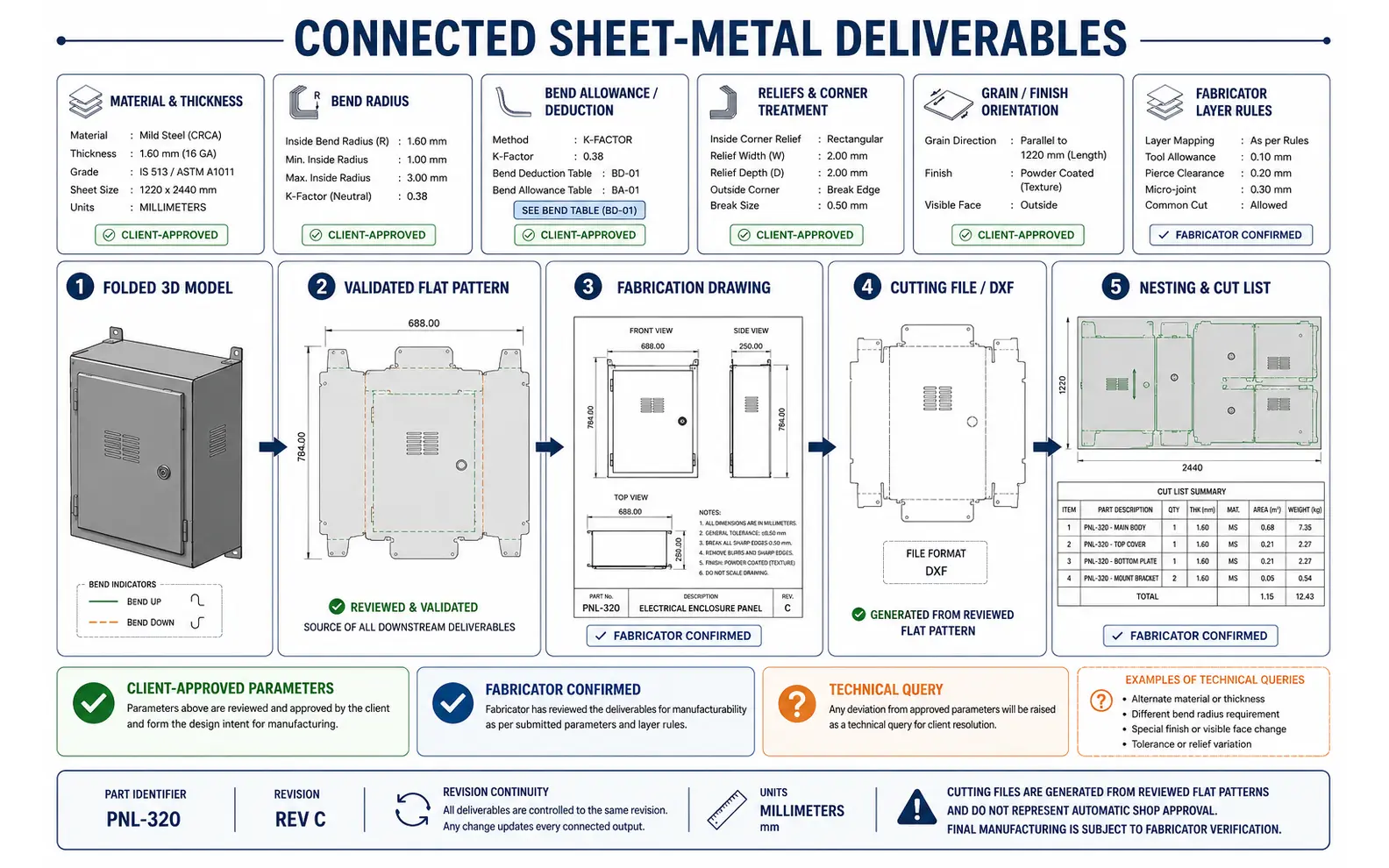
A concept model, a fabricator-reviewed flat pattern and a released drawing are not the same deliverable. The intended manufacturing route and level of approval must be understood before CAD production begins.
Our capabilities can include:
“Fabrication-ready” should not be interpreted as automatic shop approval. The fabricator must confirm material availability, machine capability, tooling, grain direction, tolerances, bend deductions and other process conditions before release.
SolidWorks sheet metal modeling can include base flanges, edge flanges, hems, jogs, bends, cut-outs, forming features and approved corner treatments. We use the client’s template, sheet-metal parameters, naming rules and expected feature structure.
An experienced modeler checks that the part can generate the required flat state within the supplied rules and that features remain connected to the intended faces or references. If a legacy solid cannot be reliably converted into a sheet-metal body, the component may require reconstruction.
For families of related parts, configurations or separate models can be created according to the client’s document-control method. A qualified reviewer checks thickness, bend data, part identifiers, properties and configuration-specific outputs before submission.
Bend allowance calculation depends on material, thickness, inside radius, bend angle and an approved K-factor, deduction or empirical shop value. Different machines and tooling arrangements can produce different results for nominally similar parts.
We can apply client-supplied formulas or fabricator-approved values and document them in the model or project instructions. We do not select a K-factor or guarantee the developed length without confirmed process information.
Bend table creation can organise approved values for repeated use across a material and thickness range. The source, units, applicability and revision of each table must be recorded so it is not applied outside its validated conditions.
Flat pattern development begins with a checked folded model and confirmed sheet-metal parameters. We review bend direction, relief geometry, formed features, cut-outs and any client-specified grain or finish orientation.
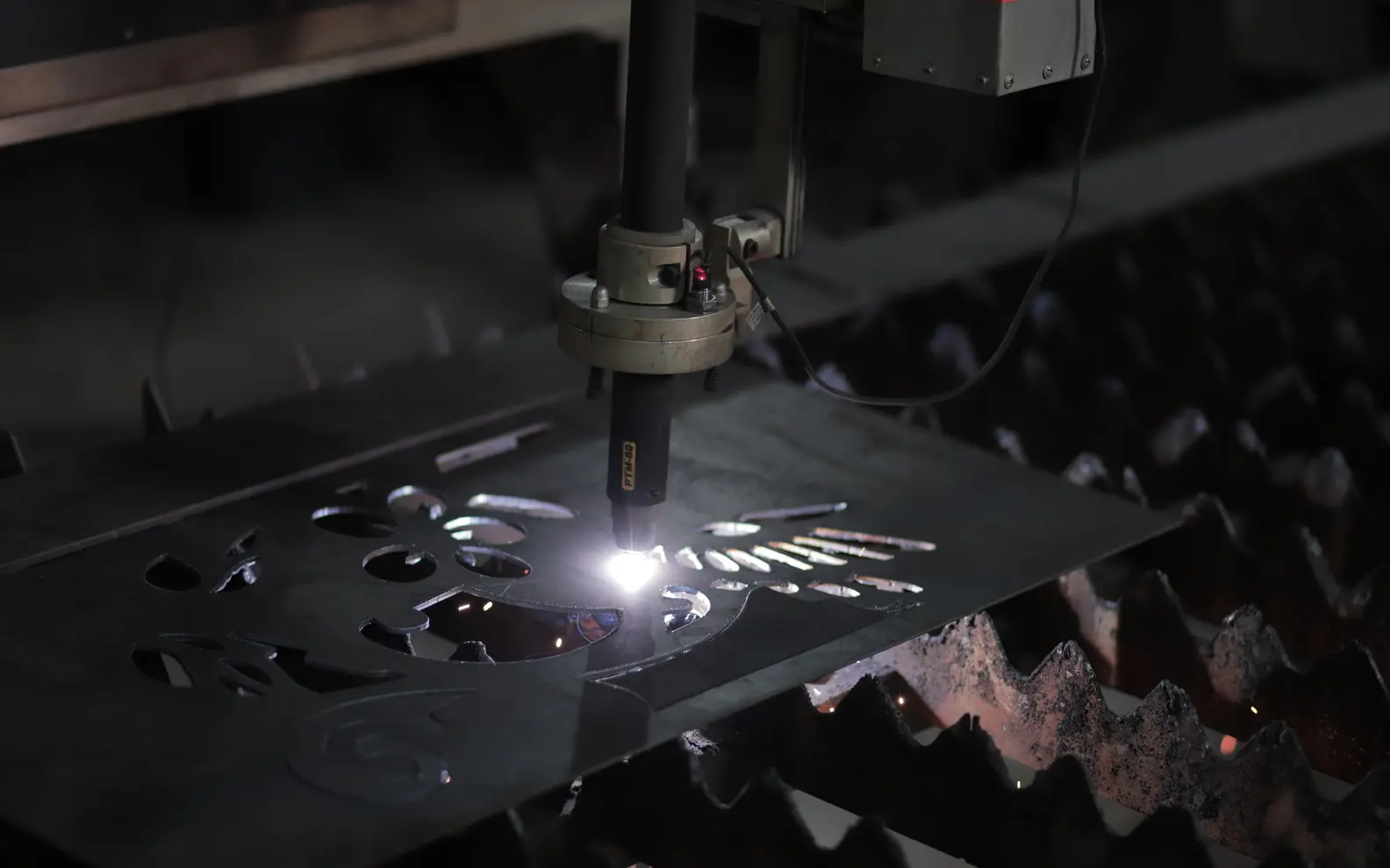
DXF files for laser cutting can be exported from approved flat patterns using the required layers, units and line treatment. Text, bend lines, etching geometry or part identifiers are included only according to the fabricator’s import requirements.
Laser, plasma, waterjet and punching workflows may require different conventions. We recommend a sample export and fabricator confirmation before producing a large batch. The cutting supplier remains responsible for CAM settings, lead-ins, kerf, machine programming and final process validation.
Sheet metal nesting drawings can help arrange approved profiles within specified stock sheets. The scope should define sheet size, edge clearance, part spacing, rotation, grain direction, quantity and whether common-line cutting is permitted.
Nesting prepared for planning is not a substitute for machine-specific CAM optimisation. Scrap handling, clamps, heat effects, cutting sequence and remnant management require fabricator input.
Cut and shear lists can summarise approved blanks, profiles, quantities and materials for suitable components. An experienced coordinator checks that identifiers and quantities align with the issued part or assembly register, while a qualified checker reviews the final list against the approved source package.
Enclosure design services can support control cabinets, equipment covers, access panels, guards and housings based on approved layouts and engineering criteria. Models may include removable panels, doors, hinges, purchased hardware and interface cut-outs.
Requirements for ventilation, ingress protection, electrical clearance, safety, sealing, structural capacity and compliance must be defined and approved by the client. We can incorporate authorised component envelopes and mounting information, but do not certify the completed enclosure against local codes or product standards.
Sheet metal fabrication drawings may show formed views, flat references, bend information, dimensions, weld or fastener notes and assembly relationships. All technical requirements are reproduced from approved instructions.
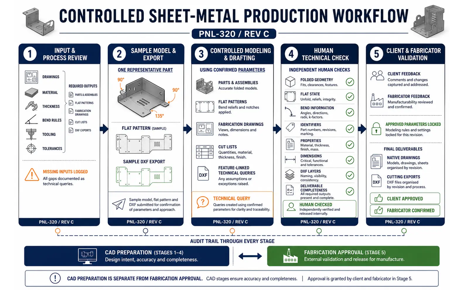
We examine drawings, models, material data, thickness, bend rules, tooling information, tolerances and required outputs. Missing manufacturing inputs are listed before flat-pattern production.
For unfamiliar shop standards or large packages, a representative part and cutting file can be submitted for client and fabricator confirmation.
Parts, flat patterns, drawings and approved lists are created using the confirmed parameters. Queries remain connected to the relevant feature or file.
Folded geometry, flat state, bend information, identifiers, properties, dimensions, layers and deliverable completeness are reviewed.
Comments are incorporated after the authorised reviewers confirm design and process-dependent matters. Final files are packaged using the agreed revision and naming structure.
This workflow supports sheet metal design and drafting outsourcing services without confusing CAD preparation with fabrication approval.
AI-assisted tools may help classify part drawings, read title-block information, compare file registers and prepare repetitive properties or cut-list data for validation. These activities can improve efficiency across large product families.
AI does not select a bend deduction, invent a missing radius, optimise machine settings or approve a cutting file. Every output remains subject to human checking and the client’s fabrication review. This combination supports qualified sheet metal design and drafting services while keeping process authority clearly assigned.
A known set of components, enclosures or assemblies can be scheduled with sample approval and defined drawing and export milestones.
Manufacturers can assign externally sheet metal design and drafting during a production peak, archive conversion or concentrated engineering-change programme.
Outsourced sheet metal design and drafting support can manage continuing brackets, panels, guards and approved variants. A current parameter and revision register helps maintain consistency.
As an experienced sheet metal design and drafting service provider, we request actual fabricator rules whenever flat-pattern or cutting outputs are required. Generic settings may not reflect the intended manufacturing process.
Sheet-metal assignments often cross design offices, suppliers and fabrication sites. We align templates, bend conventions, units, material callouts and review milestones with the client’s destination workflow before preparing production drawings.
Some clients assign externally a single enclosure range, while others extend capacity for recurring part modeling and drawing updates. We keep engineering questions, process confirmations and final production files separated throughout the workflow.
The right sheet metal design and drafting solution depends on material, forming process, source quality, output requirements and fabricator standards. Organisations comparing a sheet metal design and drafting solutions company India can provide should verify how bend data, flat patterns and shop-specific exports will be checked.
Using our fabricator’s bend table made the difference. The team tested the difficult parts first and waited for confirmation before releasing the full product family.
Stefan K., Electrical Enclosure Engineering Lead, Germany
The cutting files now match the new supplier’s import conventions, while our original model structure remains intact. Batch reviews were easy to follow.
Lerato D., Manufacturing Projects Engineer, South Africa
The monthly workflow handles our variable panel workload without weakening our own approvals. Questions about hardware or bends come back before files are finalised.
Michael J., Product Engineering Manager, United States
We can apply client- or fabricator-approved formulas, K-factors, deductions and bend tables. Reliable results require confirmed material, thickness, radius, tooling and forming-process information.
Yes. We can export reviewed flat patterns using the supplier’s approved layers, units and geometry rules. The fabricator remains responsible for CAM programming, kerf, lead-ins and machine validation.
Often, yes, if the geometry and thickness are suitable. Parts with inconsistent walls, complex transitions or unclear bend definitions may need reconstruction.
We can prepare nesting layouts using supplied sheet sizes, spacing and orientation rules. Machine-specific optimisation, cutting sequence, clamps, heat control and remnant strategy remain with the fabricator or CAM team.
Send a representative folded model, drawing or sketch together with the material, thickness, bend data, required outputs and fabricator conventions. We will review the information and identify the appropriate modeling and drafting process.
Request a Sheet-Metal Project Review