Electrical Floor Plans
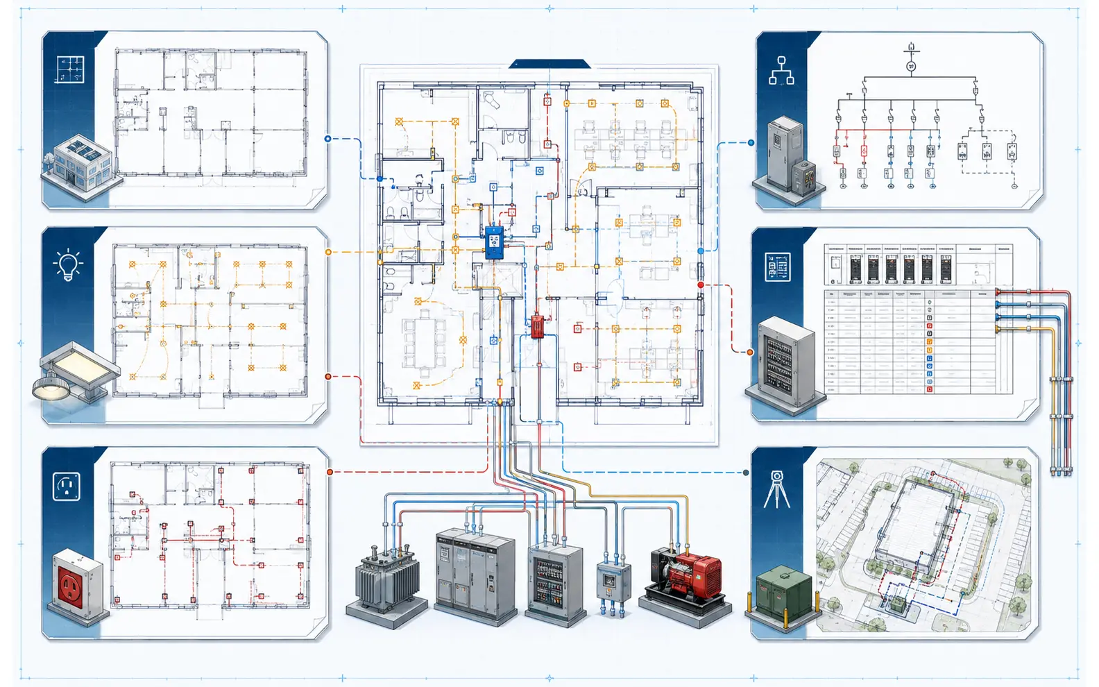
Electrical floor plans may show outlets, switches, isolators, equipment connections, panels and other approved devices. We position and annotate them according to the source mark-up, architectural background and client drafting standard.
Device identifiers, circuit references and mounting notes must remain legible at the intended plot scale. Where dense areas become unclear, enlarged plans or details can be developed from approved information.
Lighting Layout Drawings
Lighting layout drawings can include fixtures, switching groups, control zones, circuit references and emergency-lighting information. Reflected ceiling plans and interior layouts are treated as controlled backgrounds because a ceiling revision can affect several electrical sheets.
Fixture selection, lighting calculations, control strategy and emergency-lighting compliance remain with the authorised designer. We document the approved arrangement.
Power Layout Drawings
Power layout drawings may cover general outlets, dedicated supplies, isolators and equipment connections. Manufacturer or mechanical schedules can help identify connection points, but the responsible engineer confirms electrical characteristics and circuit requirements.
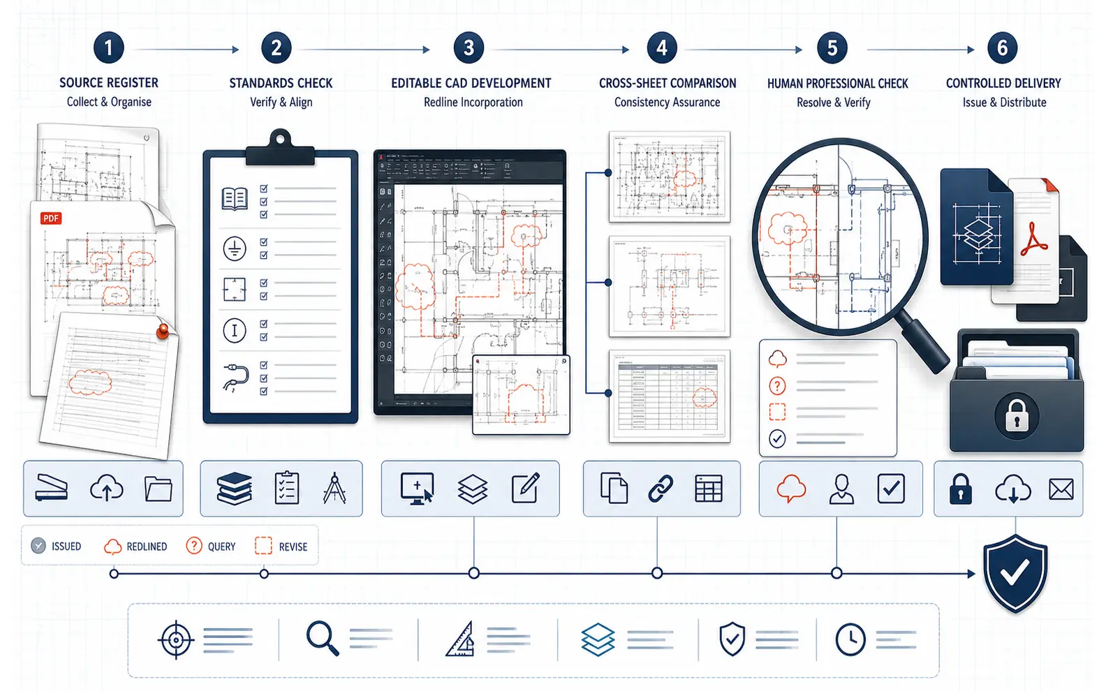
We check that equipment tags and panel references match the supplied project information. Conflicts are returned through the agreed query register.
One-Line and Control Diagrams
One-line diagram drafting converts approved distribution relationships into consistent 2D graphics. The work may include equipment identifiers, feeder references, ratings and notes supplied by the client.
Control circuit drawings can be recreated or updated from authorised schematics, terminal information and engineering mark-ups. CCSI does not develop functional logic or safety circuits from appearance alone.
Schedules and Route Plans
Panel board schedules are drafted from confirmed load, circuit, phase and protective-device information. Cable and conduit plans show approved paths, sizes and references where provided.
The checker can identify obvious differences between a schedule, one-line diagram and floor plan. Engineering validation of loads, conductor sizes, voltage drop, protection and route compliance remains outside standard drafting scope.
Electrical Site and Record Drawings
Electrical site plans may show authorised external routes, equipment, lighting, pits or connection points on the supplied survey or civil background. Coordinate and scale control is particularly important when several references are combined.
Electrical as-built drawings are updated from verified contractor redlines, survey information or client-approved site records. We do not claim that an unverified mark-up represents concealed or inaccessible conditions.