Structural Connection Design Services with Qualified Engineering Review
A correctly analysed steel frame can still face fabrication or erection problems when joints ignore actual forces, geometry or site conditions. Our structural connection design services support engineer-led projects requiring calculations, coordinated details and fabrication documentation.
The assignment can include engineered connections or production detailing from client-approved designs. Calculations are performed and reviewed by suitably qualified engineers. The engineer of record or locally licensed professional retains responsibility for jurisdictional requirements, overall design, project approval and any required signature or seal.
CAD Conversion Services India uses AutoCAD, Revit and suitable calculation tools to create traceable packages without presenting software output as independent authority.
✓ AI Powered✓ Free Pilot Batch✓ NDA Protected✓ 99.5% Quality
1500+Completed Projects
82%Returning Clients
10+Years Experience
45+Countries Served
35+Professionals Team
Project Fit at a Glance
Confirm these essentials before production begins.
Inputs
Engineer-issued design information, calculations, mark-ups and project standards
Outputs & deliverables
Structural models, drawings, schedules and material-specific detailing
Software
AutoCAD, Revit and agreed structural-production tools
Service intent
Focused production support for Structural Connection Services, with scope, source authority and review responsibility agreed before work begins.
IndustriesArchitectureConstructionManufacturingEngineeringReal EstateCountries ServedUSACanadaUKAustraliaUAEEuropean Nations45+ Countries
IndustriesArchitectureConstructionManufacturingEngineeringReal EstateCountries ServedUSACanadaUKAustraliaUAEEuropean Nations45+ Countries
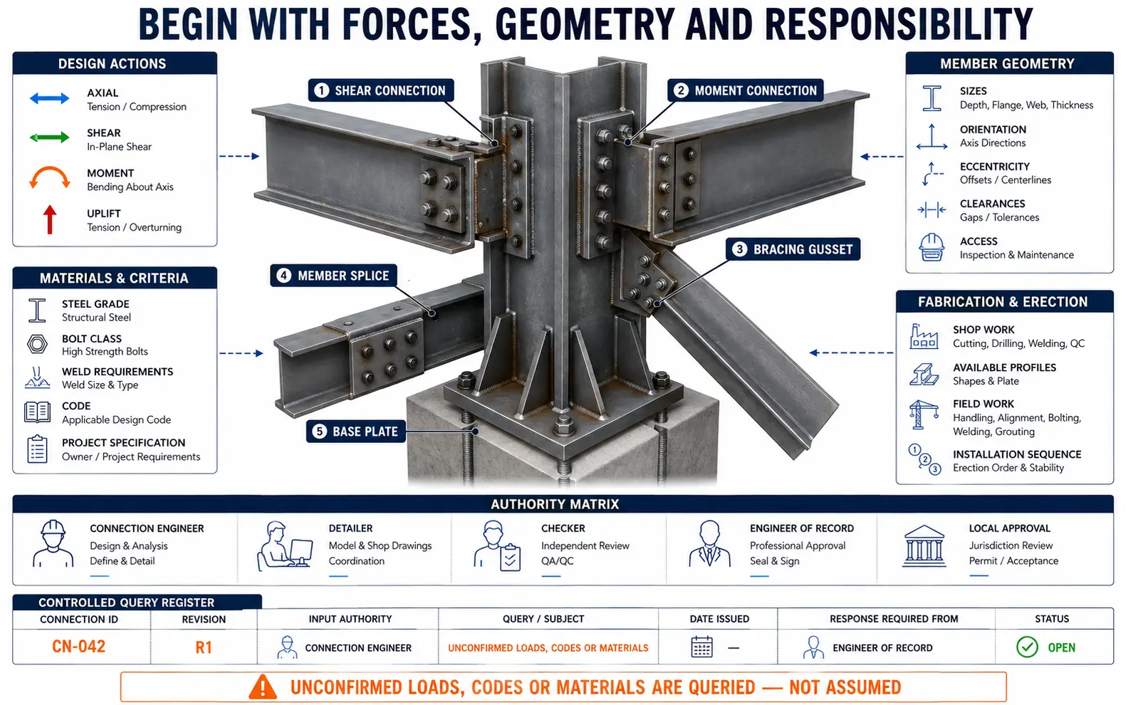
Begin with Forces, Geometry and Responsibility
Steel connection design cannot be separated from the load path or reduced to a library of attractive standard details. Even a familiar beam-to-column joint may be affected by member orientation, eccentricity, access, material thickness, edge distances, erection clearances and the forces supplied by the structural analysis.
Before production begins, we establish:
Authoritative structural drawings and model files
Design actions or approved connection loads
Applicable design standards and project specifications
Steel grades, bolt classes and weld requirements
Member sizes, orientation and connection geometry
Fabricator preferences and available profiles
Fire, fatigue, seismic or robustness requirements where relevant
Shop-versus-field connection expectations
Calculation, drawing and model deliverables
Review, approval and delegated-design responsibilities
Unconfirmed loads, codes or material assumptions are recorded as queries. AI-assisted extraction may help organise schedules or repeated connection forces, but it is not used to invent missing engineering criteria.
Engineering Calculations or Approved-Design Detailing
The service is configured through one of two clearly documented routes.
Connection Calculation Support
Connection calculation support covers defined steel joints using confirmed design actions, member information and applicable criteria. Qualified engineers select the analysis method, evaluate limit states, document assumptions and review the resulting package. Final project acceptance remains with the responsible engineer named in the authority matrix.
Detailing from Approved Connections
Where connection engineering has already been completed, our production team prepares beam connection drawings, column connection details, steel joint detailing and fabrication connection drawings from the approved design. Missing dimensions or conflicting details are returned for clarification rather than adjusted as an informal redesign.
The agreed route is stated on the proposal and drawing register. This provides a structural connection design support solution with a visible boundary between engineering judgement and drawing production.
Bolted and Welded Joint Development
Bolted connection detailing may cover bolt layouts, hole types, pitches, gauges, edge distances, plate sizes and erection access according to approved calculations and fabrication standards. Drawings distinguish shop and field work where required and maintain consistent bolt descriptions across assemblies and schedules.
Welded connection detailing may show weld type, size, length, location, preparation and approved inspection references. The engineer considers load transfer, base material, access, fabrication sequence and relevant limit states when the scope includes design.
Bolts and welds should not be selected independently from the connected components. Plates, supporting webs, flanges, stiffeners and local member effects are reviewed to the extent required by the authorised engineering brief.
Shear, Moment and Member Connections
Shear Connection Design
Shear connection design may include fin plates, double angles, end plates, seated arrangements and other project-approved configurations. The work considers the supplied actions, bolt or weld behaviour, connected-part capacity and practical detailing constraints.
Moment Connection Design
Moment connection design requires a clear understanding of force transfer, rotation demand, stiffness and the project’s structural system. End-plate, flange-plate, welded or other arrangements are evaluated under the agreed engineering basis. Seismic or special moment-frame requirements are included only when expressly defined and supported by the correct design criteria.
Bracing and Splice Connections
Bracing gussets, member splices and truss joints may introduce eccentric forces, multiple load directions or congested geometry. Our engineers and detailers coordinate the approved solution with surrounding members while documenting assumptions that require project-level confirmation.
Base Plates and Column Interfaces
Base plate connection design can address plate dimensions, bearing, anchors, welds, stiffeners, shear transfer and other defined limit states. The calculation requires confirmed column actions, concrete or grout information, support conditions and anchor criteria.
Foundation adequacy, anchor embedment, concrete breakout and reinforcing interaction must be assigned to the qualified parties responsible for those elements. If the connection scope does not include them, the exclusion is identified rather than implied to be checked.
Column splices and beam-to-column joints are similarly coordinated with member geometry and erection needs. An expert engineer reviews whether the proposed load path matches the calculation model before drawings are released for project approval.
Connection Drawings for Fabrication and Erection
The drawing set translates approved engineering information into dimensions, symbols, notes and references that a fabricator can follow. Depending on the project, deliverables may include:
Connection arrangement sheets
Beam and column interface details
Plate, angle and stiffener drawings
Bolt layouts and hole information
Weld callouts and preparation details
Base-plate and anchor layouts
Bracing, splice and truss-joint details
Connection schedules and type references
Assembly views linked to member marks
DWG, PDF, RVT and agreed exchange files
The fabricator’s title blocks, notation, numbering and shop preferences can be incorporated. Connection changes remain traceable through revision records so an updated detail is not confused with an earlier fabrication issue.
Coordination with Structural Models and Shop Drawings
Connections occupy the interfaces between analysis, member design, fabrication and erection. We compare connection geometry with the current structural model and relevant shop drawings to identify conflicts involving access, clearances, plate orientation or surrounding components.
Model-based review can help expose conditions such as:
Bolts inaccessible because of adjacent flanges or walls
Welds obstructed by plates or secondary members
Stiffeners conflicting with incoming beams
Bracing gussets overlapping service routes
Base plates extending beyond concrete supports
Erection connections lacking practical installation space
These observations are issued to the authorised team. Constructability feedback may inform a revision, but changes affecting capacity are recalculated and approved through the defined engineering process.
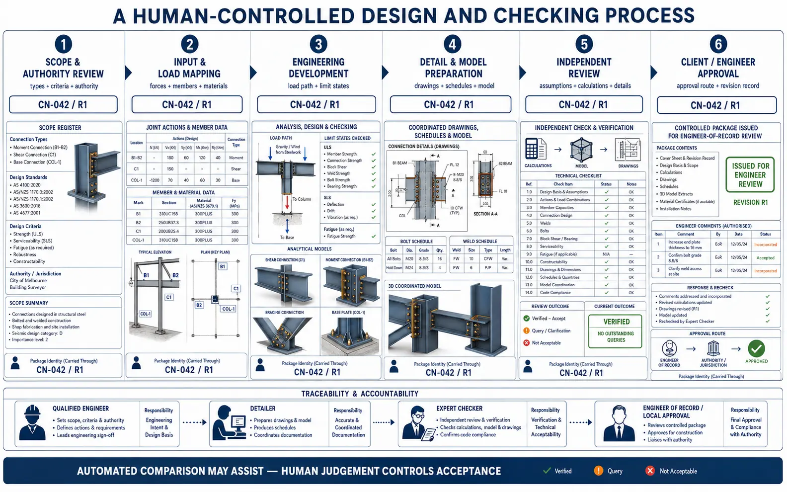
A Human-Controlled Design and Checking Process
Scope and Authority Review
We identify the connection types, design actions, applicable standards, source hierarchy and responsible approving engineers.
Input and Load Mapping
Member geometry and supplied actions are organised by joint. Missing combinations, conflicting forces and uncertain material information are recorded.
Engineering Development
For design scopes, qualified engineers select connection forms, perform checks and document the calculation logic. Drafting-only scopes begin from approved connection information.
Detail and Model Preparation
The team develops drawings, schedules and agreed model geometry using controlled member marks and connection references.
Independent Review
An expert checker reviews assumptions, load paths, calculations, dimensions, bolts, welds, plates and drawing-to-calculation consistency. Automated comparison may assist but does not approve the result.
Client or Engineer Approval
The package is issued through the agreed review route. Authorised comments are incorporated, recalculated where necessary and rechecked before final delivery.
Quality Review Focused on Joint Behaviour
Checks may cover:
Correct member sizes, orientations and material grades
Connection actions and governing combinations
Bolt class, diameter, layout and hole type
Weld type, length, size and accessibility
Plate dimensions, thicknesses and edge distances
Supporting-member and connected-part effects
Stiffener, continuity-plate and doubler requirements
Eccentricities and secondary forces
Drawing, model and calculation references
Revision status and unresolved engineering queries
Our professional structural connection design support services are delivered within the agreed calculation and approval scope. The review does not extend to unrelated structural elements unless they are expressly included.
Offshore Connection Support with Clear Governance
Our offshore structural connection design support services can provide additional calculation and detailing capacity for engineering consultancies, steel contractors and fabricators. Packages can be divided by connection type, building zone, fabrication sequence or drawing release.
Clients may outsource structural connection design support for a defined backlog or use structural connection design support outsourcing services across several projects. An offshore arrangement remains governed by named reviewers, confirmed inputs and documented issue status.
As an expert structural connection design support service provider, we keep assumptions and exclusions visible. Geographic delivery does not remove the need for professional engineering review or jurisdiction-specific approval.
Structural Connection Services Project Case Studies
Project 1: Moment Connections for a Long-Span Airport Canopy
Volume
62 primary moment joints and 148 secondary steel connections
Problem
A British steel contractor was fabricating a curved entrance canopy whose connection zones combined sloping rafters, architectural cladding limits and restricted access for field welding. Standard details did not suit several highly visible joints.
Solution
Qualified engineers grouped the joints by geometry and supplied actions, then developed end-plate and welded arrangements within the approved structural basis. Detailers coordinated bolt access, plate edges and stiffener positions with the cladding model. Non-standard joints were issued first for the contractor’s engineer and workshop to review.
Outcome
The contractor received calculation-backed details that fitted the architectural envelope and fabrication sequence. Early workshop input was incorporated before the remaining joint families were documented.
Title
Technical Director
Industry
Transport Infrastructure
Country
United Kingdom
Project 2: Base Plates and Bracing Joints for a Mineral-Processing Building
Volume
44 column bases, 96 bracing joints and 18 equipment-support connections
Problem
A South African industrial project had large horizontal equipment actions and several column bases close to concrete edges. The steel fabricator needed clarity about which checks belonged to the steel connection package and which remained with the civil foundation designer.
Solution
We created an interface register before calculation. The connection team evaluated the authorised plates, anchors, welds and gussets using confirmed actions, while concrete edge reinforcement and foundation adequacy were assigned to the client’s civil engineer. Drawings cross-referenced every external dependency instead of implying complete foundation verification.
Outcome
Steel and concrete responsibilities were resolved before fabrication release. The fabricator obtained coordinated details, and the civil engineer received the reactions and anchor demands needed for the separate foundation review.
Title
Structural Package Manager
Industry
Mining and Minerals Processing
Country
South Africa
Project 3: Recurring Connection Calculation Capacity for Small Steel Buildings
Volume
25–40 connection types per monthly release
Problem
A Canadian engineering consultancy managed frequent warehouses, mezzanines and equipment platforms. Its senior engineers were spending too much time formatting repetitive connection calculations during demand peaks.
Solution
We established a recurring workstream based on a project-specific load and responsibility sheet. Qualified engineers prepared calculation packages and marked-up connection sketches; a separate checker reviewed the results before they returned to the consultancy’s engineer of record. Approved changes were logged by joint identifier.
Outcome
The consultancy gained predictable technical capacity without transferring its local approval duties. Standardised submission records shortened review time while project-specific forces and geometry remained visible.
Title
Engineering Operations Lead
Industry
Structural Engineering Consulting
Country
Canada
Structural Connection Services Client Feedback
“
The difficult canopy joints were released early enough for our workshop to comment. That practical review saved us from discovering access problems after the steel was cut.
Oliver H., Technical Director, United Kingdom
“
The interface register clearly separated the steel checks from the concrete work. Both engineering teams knew what they had to confirm before fabrication.
Thabo M., Structural Package Manager, South Africa
“
Their recurring calculation support is organised around our engineer-of-record process. Assumptions are stated, comments are traceable and nothing is issued as locally approved without us.
Émilie G., Engineering Operations Lead, Canada
Questions About Structural Connection Services
Can you design connections without connection forces?+
Connection actions must be supplied or derived within a separately authorised analysis scope. We do not assume unconfirmed loads. The responsible engineer must also confirm the applicable combinations, design basis and relationship to the overall structural system.
Do you provide connection calculations and drawings?+
Yes, when both are included in the agreed scope. We can also prepare drawings from connection calculations already approved by the client. Deliverables and engineering responsibilities are stated before work begins.
Can you follow a fabricator’s preferred connection types?+
Preferred details can be considered if they suit the supplied actions, geometry and applicable criteria. An engineer must verify their adequacy; familiarity or previous use does not automatically make a detail appropriate for a new project.
Are your connection packages locally signed or sealed?+
Connection documents remain subject to the project engineer’s release procedure. Where local law calls for certification, a seal or a signed calculation package, the accountable licensed practitioner must provide it under a separately confirmed arrangement.
Start with a Representative Joint Package
Send us structural drawings, connection forces, project specifications, preferred joint types, required outputs and the intended approval route. We will identify missing inputs and recommend a suitable production and engineering workflow.
Whether you need to outsource one calculation package or establish recurring offshore capacity, the first release should confirm both technical expectations and responsibility boundaries.