Capture Package Assessment
We inspect file formats, registration information, coverage, units, coordinates and representative data quality. The client confirms scan authority and survey limitations.
Reality-capture data can document millions of measured points, but a point cloud is not yet a building model. Before it can support renovation, coordination or record documentation, the relevant surfaces and systems must be interpreted within an agreed accuracy, scope and model purpose.
Our point cloud to BIM services transform registered scan data into organised Revit models. We support architectural, structural and MEP project teams working with existing buildings, industrial facilities, infrastructure spaces and renovation programmes.
The client’s survey or scanning provider remains responsible for capture coverage, registration and survey control unless those responsibilities are expressly included elsewhere. Our work begins with the supplied point-cloud data and the modeling requirements agreed for the project.

Confirm these essentials before production begins.
CAD backgrounds, survey or scan data, design files and BIM standards
Purpose-defined Revit models, families, drawings, schedules and agreed exchanges
Revit, AutoCAD and approved coordination viewers
Focused production support for Point Cloud / Scan to BIM, with scope, source authority and review responsibility agreed before work begins.
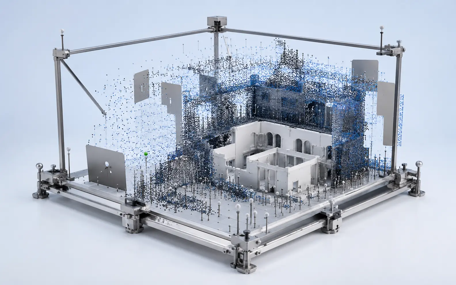
Registered point cloud modeling depends on more than point density. The data must have usable units, orientation, coordinate information and sufficient coverage for the elements required in the model.
Before production, we review:
If important areas are not visible in the supplied data, the limitation is recorded. A model cannot reliably represent geometry that the scan does not capture.
Laser scan to Revit production uses point-cloud references to establish levels, grids, major planes, building elements and visible system routes. The modeling sequence is selected according to the project’s purpose and the quality of the available scan.
A point cloud to Revit model may intentionally preserve irregular conditions rather than forcing the building into perfectly straight or level geometry. Alternatively, the client may define simplified modeling rules for specific elements.
Those choices are agreed during setup. The model should represent the required existing condition without adding complexity that does not serve the project.
Existing conditions BIM can provide a coordinated digital base for refurbishment, adaptive reuse, space planning, facility changes or record documentation.
Renovation scan to BIM assignments often require special attention to:
The model scope should distinguish measured existing conditions from proposed work. Unless otherwise defined, the supplied scan is treated as evidence of visible geometry at the time of capture—not proof of concealed construction.
Architectural point cloud modeling can include visible walls, floors, roofs, ceilings, doors, windows, stairs, rooms and selected facade or site elements.
Irregular heritage geometry, sloped surfaces and non-standard openings may require project-specific families or simplified representations. The expected treatment is confirmed using sample zones before it is applied throughout the model.
For an as-built BIM from scans assignment, the term “as-built” describes a model based on captured conditions. It does not certify concealed conditions, construction compliance or survey accuracy beyond the supplied data and agreed checks.
Structural scan to BIM can represent visible columns, beams, slabs, walls, trusses, frames and other structural elements included in the brief.
Scan data may show surface geometry but not reinforcement, concealed connections, material grade or structural capacity. Those properties are added only when supported by approved engineering information.
The model can assist structural teams with measured-condition reference, retrofit planning and geometric coordination. Engineering analysis, member verification and design approval remain with the client’s structural professionals.
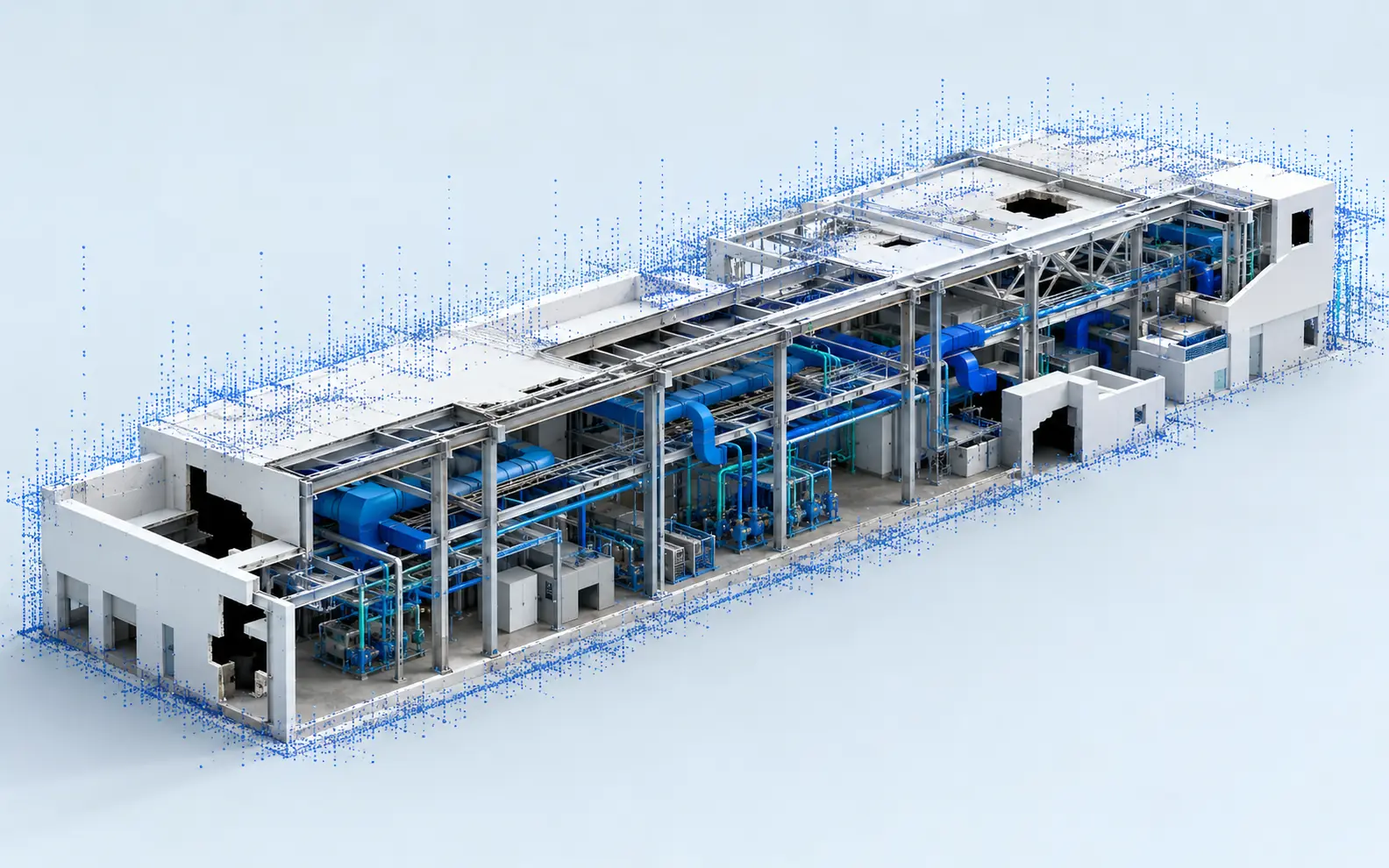
MEP scan to BIM can be particularly useful in plant rooms, ceiling voids, service corridors and industrial areas where existing routes are difficult to understand from drawings alone.
Visible ducts, pipes, cable trays, equipment and selected fittings can be modeled to the agreed detail. Small components, insulation, hangers or concealed connections may be excluded unless specifically required and sufficiently visible.
System classification and connectivity are not assumed solely from proximity. Where service identity or connection cannot be established from the scan and supporting records, the question is returned to the client.
LiDAR to BIM conversion may support buildings, warehouses, industrial facilities, facades and other measured environments captured through terrestrial or mobile scanning.
Large datasets often require zoning and model segmentation so production, review and file performance remain manageable. The project can be divided by floor, building wing, discipline or another agreed work breakdown.
Reality capture modeling is then carried out progressively against those zones. This makes data gaps and review comments easier to locate than treating the entire point cloud as one undifferentiated package.
Model detail describes what is represented. Accuracy or tolerance describes how closely that representation should align with the point-cloud evidence. A highly detailed family is not useful if its position or dimensions do not meet the project requirement.
We therefore agree:
These definitions create a practical point cloud and scan to BIM solution and give the reviewer an objective checking basis.
Model validation may include overlaying Revit views against the point cloud, reviewing sections through important zones and checking representative dimensions or element positions.
Colour-based or visual deviation review can help identify areas where modeled surfaces move outside the agreed tolerance. The checking approach depends on available software, project size and required accuracy.
Not every point is compared individually. Instead, the quality plan defines critical elements, sample locations, complex zones and known risk areas that require focused checking.
An experienced reviewer examines the model and supporting issue records before submission. Clients assessing an technical point cloud and scan to BIM service provider should confirm that its checking method matches the required accuracy and model use. Where the scan itself is unclear, the limitation remains visible to the client.
AI-supported processes may help classify scan files, organise zones, compare metadata or identify areas that warrant closer inspection. Automation may also support repetitive preparation for large reality-capture datasets.
AI does not authorise geometry to be invented across scan gaps. It is not used to infer concealed systems, select structural properties or certify survey accuracy.
Human modelers interpret the visible point-cloud evidence, and a qualified checker reviews the output against the agreed scope. Additional experienced attention is applied to complex zones or elements identified in the quality plan. This keeps the use of automation limited, traceable and appropriate to the project.
We inspect file formats, registration information, coverage, units, coordinates and representative data quality. The client confirms scan authority and survey limitations.
Required disciplines, elements, accuracy, detail, file segmentation, parameters and outputs are agreed. A complex sample zone may be selected.
Levels, grids, coordinates, links and model zones are established. The point cloud is organised for manageable viewing and production.
Visible elements are developed zone by zone. Scan gaps, uncertain geometry and conflicting supplementary records are logged.
Representative sections, views and critical areas are compared with the scan under the agreed checking method.
Approved comments are incorporated before native models, documentation, exports and limitation records are delivered.
Organisations may assign externally point cloud and scan to BIM when a project contains large captured datasets, multiple buildings or specialist production work that would otherwise consume internal BIM capacity.
Our offshore point cloud and scan to BIM services can support one building, selected zones, one discipline or a phased portfolio programme. Project packages can be submitted by level, area or model milestone.
Some clients assign externally a complete existing-condition model, while others retain coordination internally and use our point cloud and scan to BIM outsourcing services for defined production zones.
The offshore arrangement supports qualified model production but does not shift responsibility for survey registration, design decisions or licensed approval unless a separate scope expressly states otherwise.
Deliverables may include:
File versions, coordinates, naming and exports are agreed before submission. Our qualified point cloud and scan to BIM services return an organised model package rather than an unexplained RVT file.
Rather than forcing the building into repeated modern geometry, the team agreed where irregularity should be preserved and where simplified representations were acceptable.
The team was careful not to connect services that disappeared from the scan. That honesty made the model more useful because our site team could focus on the exact areas that still needed investigation.
Oliver J., Healthcare BIM Coordinator, United Kingdom
The irregular geometry was handled with impressive care. Thank you for preserving the character of the existing station while keeping the Revit model practical for our renovation team.
Haruto S., Heritage Design Architect, Japan
We received more than a model—the limitation register showed where further survey work was needed before automation planning. That saved our engineers from relying on incomplete areas.
Thabo M., Retrofit Programme Manager, South Africa
We can review common registered formats such as RCP, RCS and E57, subject to project software and data-transfer requirements. Representative files should be tested before full production.
Our core service is BIM model production from supplied scan data. Site capture, survey control and registration remain with the client or scanning provider unless a separate arrangement has been confirmed.
Yes. The scope can cover architectural, structural, MEP or selected element groups. Visibility, minimum size, accuracy and exclusions should be defined before modeling.
Yes. You can assign externally a representative room, bay, floor or complex service zone to confirm model treatment, accuracy and deliverables before the wider dataset proceeds.
Send us representative registered point-cloud data, the required Revit version, target elements, accuracy expectations and intended model use. We will assess the information and recommend a controlled production solution.
Request a Point-Cloud-to-BIM Review